Controlling the operation of a respiratory gas monitor

a technology of respiratory gas monitor and operation method, which is applied in the direction of operating means/releasing devices for valves, instruments, diagnostic recording/measuring, etc., can solve the problems of limiting the reliability of a rgm, limiting the operating life of the pump, and relatively short pump operating life, so as to avoid unnecessary wear of the gas pump, improve the reliability of the rgm, and eliminate the operation of the sample gas pump

Active Publication Date: 2012-07-31
GENERAL ELECTRIC CO
View PDF6 Cites 8 Cited by
  • Summary
  • Abstract
  • Description
  • Claims
  • Application Information

AI Technical Summary

Benefits of technology

[0004]The purpose of the present invention is to eliminate unnecessary operation of the sample gas pump in a RGM. Another purpose of the invention is to improve the reliability of the RGM by avoiding unnecessary wear of the gas pump.

Problems solved by technology

Regardless of the type of the actuator and the valves, moving mechanical parts in the pump are subjected to stresses and wear, which limit the operating life of the pump.
The relatively short operating life of the pump—typically in the order of 5000 hours—is often one of the main factors limiting the reliability of a RGM.
When the pump in a RGM fails, the sample gas flow may stop completely or decrease to an unacceptable level.
The value of such alarm is quite limited, however, because monitoring of respiratory gases is no more possible after a pump failure.
In some RGMs, low flow may remain undetected and lead to measurement errors that may compromise patient safety.
Even if the RGM could be manually switched to Standby mode, users tend to forget it, because they are busy with more important tasks, when disconnecting a patient from the RGM.
If a gas pump is running for 12 hours a day, it typically fails about twice in three years, which means that it is one of the main factors limiting the “mean time between failures” of a RGM.
This means that the replacement is costly and it may take a substantial time to have the RGM repaired after a pump failure.

Method used


Image

  • Controlling the operation of a respiratory gas monitor
  • Controlling the operation of a respiratory gas monitor
  • Controlling the operation of a respiratory gas monitor

Examples


Embodiment Construction

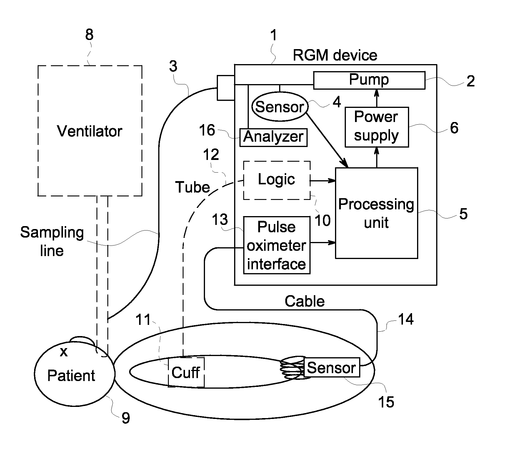
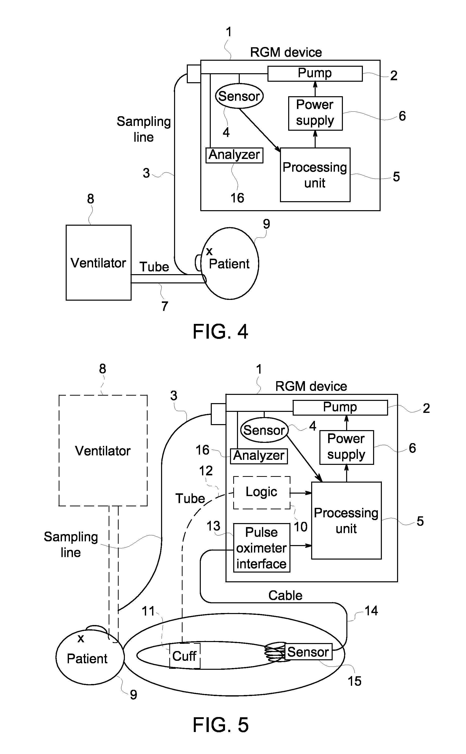
[0014]The known respiratory gas monitor (=RGM) devices 1 comprise at least one respiratory gas analyzer 16 of a type applicable to analyze a gas component or gas components of the respiratory gas, i.e. gas components like CO2 and / or oxygen and / or NO and / or NO2 and / or N2O and / or other anesthetic gas component(s), which respiratory gas is fed to the patient and / or exhaled by the patient along a breathing tube 7. For this breathing purpose one end of the breathing tube 7 is connected to a ventilator device 8 and to the other end of the breathing tube 7 is connected to the patient 9. A gas sampling line 3 that is a thinner tube is flow-connected to the wider breathing tube 7. This gas sampling line 3 can be connected to the patient 9 also without the breathing tube 7 and the ventilator device 8. Accordingly, it is question about a diverting type or side flow monitoring of a patient. Because the respiratory gas analyzer 16 and the ventilator device 8 can be of any type appropriate for th...


PUM


Abstract

A method for controlling a respiratory gas monitor device, which includes at least one respiratory gas analyzer, a gas sampling line, a gas pump for sucking sample(s) of respiratory gas from the gas sampling line. Also included are a power supply and a processing unit, and a pressure sensor connected to the gas sampling line and electrically connected to the processing unit. A minimum value and a maximum value in a signal from the patient are detected by the processing unit, and a difference between the minimum value and the maximum value is calculated. The value of this difference is compared with a predetermined threshold value. If the calculated difference is below the threshold value, the pump is switched off or kept non-operating by the processing unit. If the calculated difference is over the threshold value, the pump is switched on or kept operating by the processing unit.

Description

FIELD OF THE INVENTION[0001]The invention relates a method for controlling the operation of a respiratory gas monitor, which comprises at least one respiratory gas analyzer, a gas sampling line connected to a breathing tube that feeds respiratory gas to and from a patient, a gas pump for sucking a sample flow of respiratory gas from said breathing tube through said gas sampling line, a power supply and a processing unit, and either a pressure sensor connected to said gas sampling line and generating an electrical signal connected to said processing unit, or at least one other patient monitor device capable to detect values of at least one physiological signal from said patient, said other patient monitor detection-connected to said patient and electrical-signal-connected to said processing unit.BACKGROUND OF THE INVENTION[0002]Respiratory Gas Monitors (=RGM) of the diverting type have a gas pump for drawing a flow of sample gas from the airway of the patient to the RGM. The sample g...

Claims


Application Information

Patent Timeline
Patent Type & Authority Patents(United States)
IPC IPC(8): F16K31/02A62B7/00
CPCA61B5/0205A61B5/087A61M16/085A61M2205/13A61M2205/50A61M2230/04A61M2230/205A61M2230/30A61M2230/432A61M2230/435A61M2230/437A61M2230/60
Inventor KARLSSON, KAI
Owner GENERAL ELECTRIC CO
Why Eureka
Try Eureka