Telescopic tube set for bridge transport system

a technology of telescopic tubes and transport systems, applied in the direction of machine supports, curtain suspension devices, manufacturing tools, etc., can solve the problems of poor resistance to bending and torsion, injury or damage, difficult to achieve accurate control, etc., and achieve the effect of stable extension and retraction and excellent strength against bending

Active Publication Date: 2012-07-31
KOREA HYDRO & NUCLEAR POWER CO LTD +1
View PDF7 Cites 5 Cited by
  • Summary
  • Abstract
  • Description
  • Claims
  • Application Information

AI Technical Summary

Benefits of technology

[0014]Another object of the invention is to provide a safe and secure telescopic tube set for a bridge transport system capable of: achieving stable extension and retraction through a configuration in which each tube of the telescopic tube set has a uniform side wall thickness such that the center of gravity of the tube is centrally positioned without being biased to one side of the tube; exhibiting excellent strength against bending and torsion through a configuration in which each tube of the telescopic tube set has a cylindrical shape; and preventing malfunction of the telescopic tube set caused by contamination of extension / retraction lines connected between adjacent tubes and a tube extension / retraction device through a configuration in which the extension / retraction lines and extension / retraction device are not exposed to the outside of the telescopic tube set even when the telescopic tube set extends to a maximum length, thereby preventing a person or other equipment from being injured or damaged by the extension / retraction lines or extension / retraction device.

Problems solved by technology

However, there may be a problem of eccentricity because only the wall of each tube where the LM guide is installed is thick, whereas the remaining walls of the tube are thin, so that the center of gravity of the tube is biased to one side of the tube.
Furthermore, there may be a structural problem of poor resistance to bending and torsion because only the wall of each tube where the LM guide is installed is thick, whereas the remaining walls of the tube are thin.
For this reason, the extension / retraction device may be contaminated by dust, etc., so that it may malfunction upon extension or retraction of the telescopic tube set.
In addition, the user or other devices may bump into the extension / retraction device, possibly resulting in injury or damage.
Moreover, such a conventional telescopic tube has a problem in that it is difficult to achieve accurate control because the extension and retraction of the telescopic tube are carried out, starting from the outermost tube and innermost tube, respectively.

Method used


Image

  • Telescopic tube set for bridge transport system
  • Telescopic tube set for bridge transport system
  • Telescopic tube set for bridge transport system

Examples


Embodiment Construction

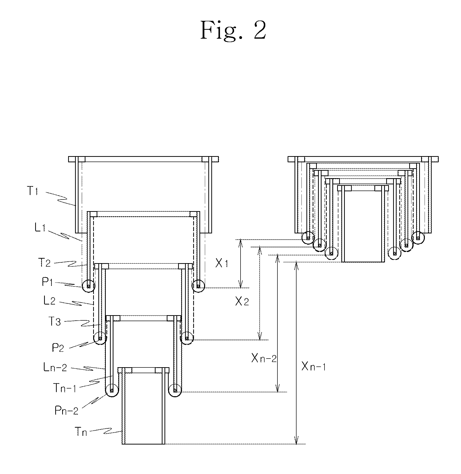
[0027]Now, a telescopic tube set according to an exemplary embodiment of the present invention will be described with reference to the annexed drawings.

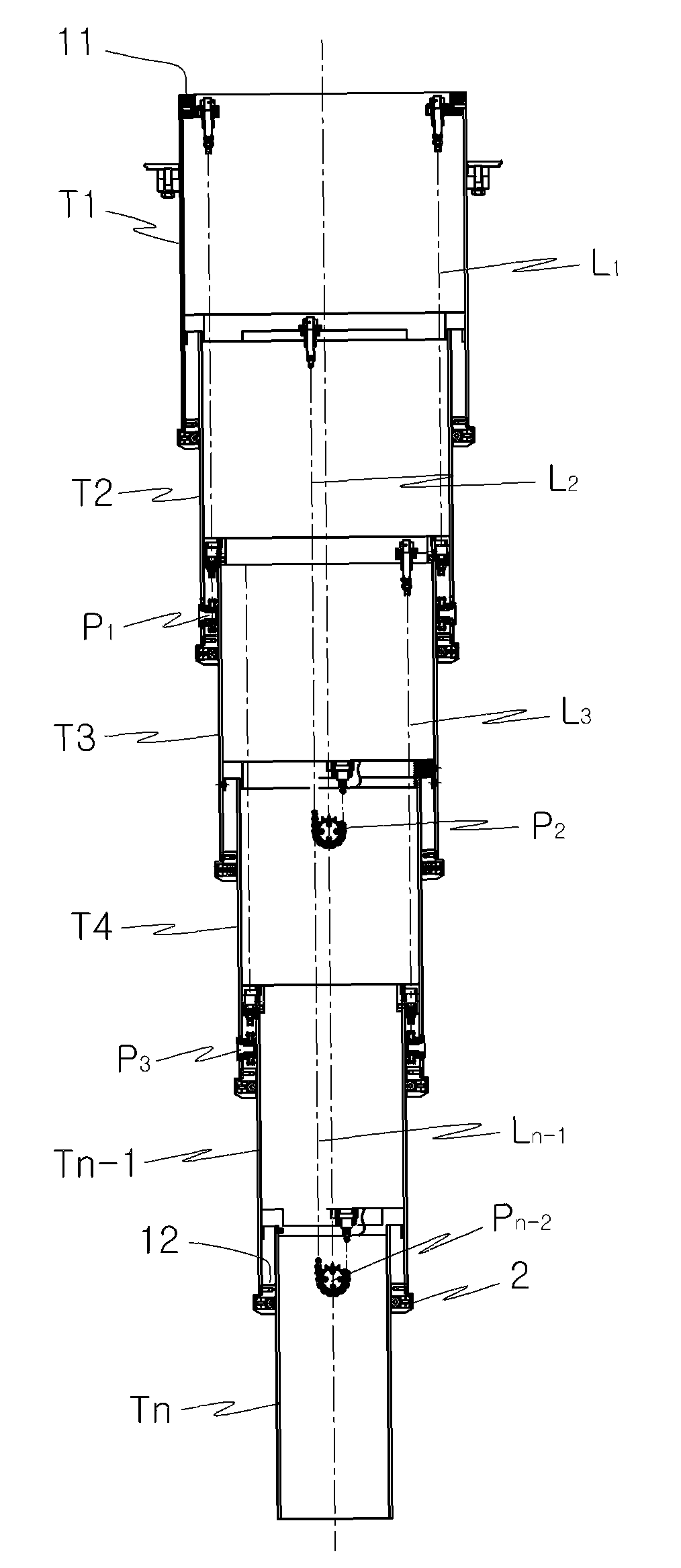
[0028]Referring to FIG. 2, a telescopic tube set according to an exemplary embodiment of the present invention is illustrated. The telescopic tube set includes a plurality of cylindrical tubes T1 to Tn, and an extension / retraction device for extending or retracting the tubes T1 to Tn. The extension / retraction device is installed within the tubes T1 to Tn.

[0029]In detail, the telescopic tube set according to the illustrated embodiment of the present invention includes cylindrical tubes T1 to Tn each having an upper end, at which an upper ring 11 is mounted, and a lower end, at which a lower ring 12 is mounted. The cylindrical tubes T1 to Tn have different diameters. The telescopic tube set also includes pulleys P1 to Pn-2 mounted to respective inner wall surfaces of a part of the tubes T1 to Tn, namely, the tubes T2 to and extension / r...


PUM

PropertyMeasurementUnit
diametersaaaaaaaaaa
cylindrical ring shapeaaaaaaaaaa
gravityaaaaaaaaaa

Abstract

A telescopic tube set for a bridge transport system is disclosed. The telescopic tube set includes cylindrical tubes each having an upper end, at which an upper ring is mounted, and a lower end, at which a lower ring is mounted, the cylindrical tubes having different diameters, pulleys mounted to respective inner wall surfaces of a part of the tubes, and extension / retraction lines each having an end connected to the upper ring of a corresponding one of the tubes, and an opposite end connected to the upper ring of another corresponding one of the tubes while extending around the pulley mounted to the tube interposed between the corresponding tubes. A plurality of bearings are installed at the lower ring to guide the tube, at which the lower ring is mounted, such that the tube extends or retracts straight in a longitudinal direction.

Description

BACKGROUND OF THE INVENTION[0001]1. Field of the Invention[0002]The present invention relates to a telescopic tube set for a bridge transport system, and more particularly to a telescopic tube set for a bridge transport system capable of[0003]2. Description of the Related Art[0004]A bridge transport system is used to move remote handling equipment such as a servo manipulator and tools to an interior of a hot cell.[0005]Such a bridge transport system may include main modules to move in x, y and z-directions in a hot cell, which include a girder, a trolley and a telescopic tube set, and auxiliary modules including a power and signal cable management system, remote handling equipment, a tool attachment die, hoist crane, etc.[0006]An example of a telescopic tube moving device, which is included in the bridge transport system configured as mentioned above, is shown in FIG. 1.[0007]As shown in FIG. 1, the telescopic tube moving device, which moves a telescopic tube set 100, includes a gir...

Claims


Application Information

Patent Timeline
Patent Type & Authority Patents(United States)
IPC IPC(8): A47H1/10
CPCB25J5/04B25J18/025F16C29/045F16C2322/59
Inventor LEE, HYO JIKPARK, BYUNG SUKLEE, JONG KWANGKIM, KI HO
Owner KOREA HYDRO & NUCLEAR POWER CO LTD
Why Eureka
Try Eureka