Injection mold for forming a light guide plate

a technology of injection molds and light guides, which is applied in the direction of instruments, manufacturing tools, food shaping, etc., can solve the problems of affecting the size, light efficiency, mechanical and optical characteristics, etc. of the lcd, and the related art light guide plate does not uniformly distribute the light to the lcd panel, so as to prevent the deformation minimize the residual stress of the molded article, and minimize the effect of the residual stress

Active Publication Date: 2012-08-07
LG DISPLAY CO LTD
View PDF1 Cites 15 Cited by
  • Summary
  • Abstract
  • Description
  • Claims
  • Application Information

AI Technical Summary

Benefits of technology

[0015]Another object of the present embodiment is to provide an injection mold that minimizes the residual stress of a molded article by modifying a shape of a gate portion guiding resin from an injection portion, so as to prevent the deformation of the molded article.
[0016]Yet another object of the present embodiment is to provide a light guide plate and corresponding LCD using the injection mold having the modified shape of the gate portion to minimize its residual stress, thereby improving the uniformity of an optical pattern.

Problems solved by technology

In addition, the backlight unit consumes 70% or more of the driving power used in the LCD device, and therefore affects the size, the light efficiency, mechanical and optical characteristics, etc. of the LCD.
That is, the related art light guide plate does not uniformly distribute the light to the LCD panel.
However, the related art injection molding process for the light guide plate 30 has a problem in that residual stresses, such as a stress caused by a resin-filling unbalance and the stress generated by areas of the plate 30 cooling at different rates exist within the molded light guide plate 30.
Further, these residual stresses cause the light guide plate 30 to be deformed over time because of the high temperature they operate in.
The changed liquid crystal alignment causes a picture quality defect such as a ripple phenomenon.

Method used


Image

  • Injection mold for forming a light guide plate
  • Injection mold for forming a light guide plate
  • Injection mold for forming a light guide plate

Examples


Embodiment Construction

[0039]Reference will now be made in detail to the embodiments of the present disclosure, examples of which are illustrated in the accompanying drawings. Wherever possible, the same reference numbers will be used throughout this disclosure including the drawings to refer to the same or like portions.

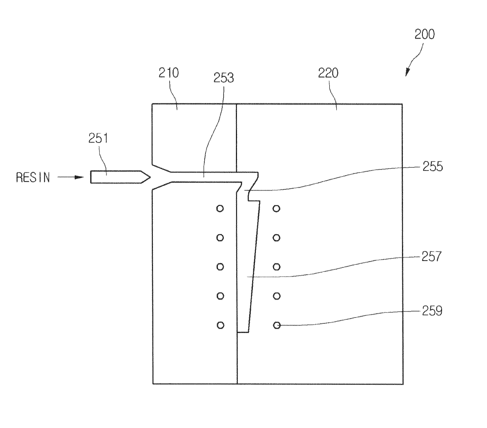
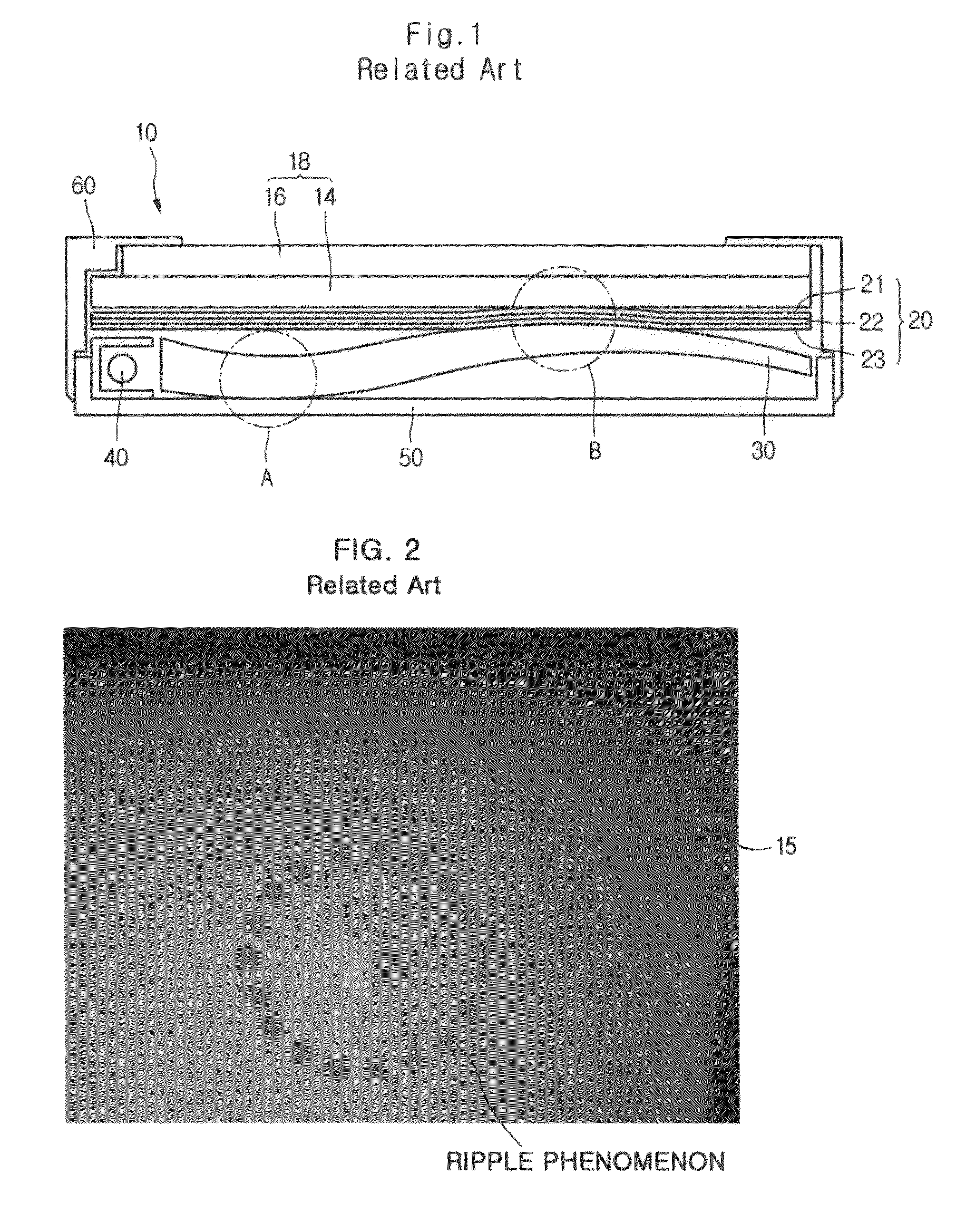
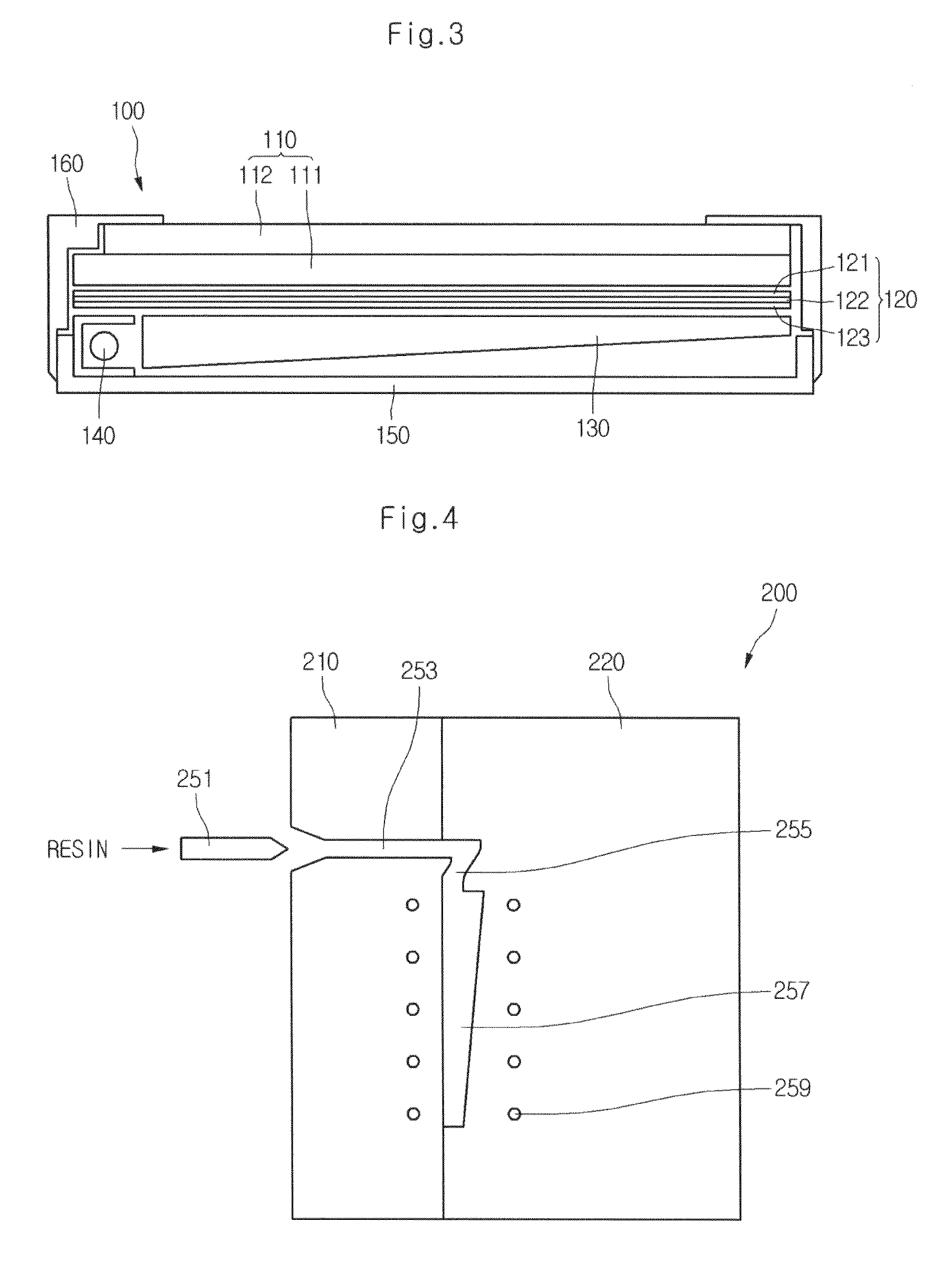
[0040]The inventor of the present invention advantageously determined that one of the causes that generate the bending of the light guide plate 30 is that the gate structure of the mold through which resin is injected upon injection molding is narrow and thick. Therefore, when resin is injected into the light guide plate mold, a portion of the cavity remote from the gate is not sufficiently filled with the resin as the resin is filled into a wide cavity from the narrow gate. As a result, the brightness provided by the molded light guide plate is decreased at a portion of the light guide plate which is not properly formed, thereby causing the brightness uniformity of the entire LCD panel t...


PUM

PropertyMeasurementUnit
thicknessaaaaaaaaaa
brightnessaaaaaaaaaa
widthaaaaaaaaaa

Abstract

An injection mold for forming a light guide plate including a first block, a second block configured to face the first block, a forming portion included between the first and second blocks facing each other and having a shape of the light guide plate, an injection portion formed at the first block and configured to receive injected resin for forming the light guide plate, and a gate portion configured to guide the injected resin from the injection portion to the forming portion. Further, a width of a first end portion of the gate portion that is connected to the forming portion is 50%-80% of a width of the forming portion.

Description

CROSS-REFERENCE TO A RELATED APPLICATION[0001]This application claims priority under 35 U.S.C. 119 to Korean Patent Application No. 10-2007-0040575, filed in Korea on Apr. 30, 2008, which is hereby incorporated by reference in its entirety.BACKGROUND OF THE INVENTION[0002]1. Field of the Invention[0003]The present application relates to an injection mold that minimizes a residual stress of a molded light guide plate, a light guide plate fabricated using the same, and a Liquid Crystal Device (LCD) device having the light guide plate.[0004]2. Description of the Related Art[0005]An LCD is advantageous over a Cathode Ray Tube (CRT), because an LCD can be made to have a small size, is light-weight and provides a better overall picture quality. Thus, LCDs are now used in many devices such as televisions, computers, etc. Further, because the LCD is a non-luminous type device, the LCD includes a backlight unit that applies a light to the rear of the LCD panel.[0006]In addition, the backligh...

Claims


Application Information

Patent Timeline
Patent Type & Authority Patents(United States)
IPC IPC(8): B29C45/73
CPCB29C45/2708B29C45/0025B29C2045/0027B29L2011/0075G02F1/1335
Inventor NAM, JI GEUN
Owner LG DISPLAY CO LTD
Why Eureka
Try Eureka