Atherectomy devices and methods

a technology of atherectomy and lumen, which is applied in the field of occluded body lumen treatment, can solve the problems of unacceptably high rate of restenosis, barotrauma to the vessel, and the embolization of a downstream vessel, and achieve the effect of preventing accidental cutting of the lumen wall

Active Publication Date: 2012-08-07
ATHEROMED
View PDF243 Cites 105 Cited by
  • Summary
  • Abstract
  • Description
  • Claims
  • Application Information

AI Technical Summary

Benefits of technology

[0019]In additional variations, the weakened section of the sweep frame comprises a varying column strength that increases in a circumferential direction away from the first radial side to prevent radial twisting of the sweep frame when deflected. Such a configuration is intended to prevent twisting or torsion of the weakened section of the sweep frame upon bending. In one variation, the sweep frame comprises struts to accomplish such preferential bending towards the first radial side and increasing column strength away from the first radial side.
[0026]As discussed herein, variations of the novel devices include one or more sweep frames and / or sweep tubes to cause deflection of the distal portion (and other portions) of the debulking device. The sweep frame improves conventional devices since it allows the catheter to stay straight when in the straight position. In other words, the sweep frame prevents the debulking catheter from developing an undesirable “bend” when the device is intended to be in a straight position. Such undesired set bends are common with conventional steerable catheters. Avoiding the undesirable set bend reduces the chance that the debulking device creates unwanted collateral damage to healthy tissue. For example, a conventional device that assumes a bend (either after multiple flexing, from an extended time in packaging, from exposure to heat) can come to rest against healthy tissue when the physician assumes that the device is straight. Clearly, activation of the conventional device in such a circumstance prevents the physician from limiting the debulking to the target tissue.
[0027]Aside from ease of construction (e.g., a simple and inexpensive construction) the sweep frame provides excellent column strength for improved forward cutting speed in straight and in deflected positions. This structure was found to prevent a failure mode where the sheath collapses onto and spiral wraps around a torque shaft. Moreover, the sweep frame provides excellent apposition force for better cutting at diameters larger than the catheter.
[0028]In addition, providing a sweep frame that must be compressed to deflect allows for selectively “tuning” the construction so that as the bending portion of the sweep frame reaches the desired maximum desired deflection, the segments forming the bending portion can mechanically interfere to prevent further bending.
[0034]Another variation of the method is to position and deflect a second bending or sweep frame along the catheter body to advance the debulking assembly in the direction set by the first sweep frame to increase the reach of the debulking assembly. The second sweep frame can provide a reaction force to the apposition force of the cutter approximated against plaque or tissue without requiring a reaction force from the catheter body interacting with the vessel wall. The second bending frame can also be used to allow precise control of the cutter angle with respect to the tissue to be debulked. A second sweep shaft can be rotated to sweep the debulking assembly.
[0036]The devices described herein may have a cutter assembly having a portion of its housing having a curved surface and where the opening forms a plane across the curved surface such that as the cutting surface rotates across the opening, a portion of the cutting surface extends out of the housing through the opening. The cutter assembly may also have various other features as described below that improve the safety of the device as it is articulated while cutting. Furthermore the cutter may have a number of features to impel or drive cut tissue into the cutter assembly for eventual removal by one or more conveying members.

Problems solved by technology

Often plaque is friable and may dislodge naturally or during an endovascular procedure, leading to embolization of a downstream vessel.
Balloon angioplasty is known to cause barotrauma to the vessel from the high pressures required to compress the plaque.
This trauma leads to an unacceptably high rate of restenosis.
Furthermore, this procedure may not be efficient for treatment of elastic-type plaque tissue, where such tissue can spring back to occlude the lumen.
On their own, stents fail to perform well in the peripheral vasculature for a variety of reasons.
A stent with the necessary structural integrity to supply sufficient radial force to reopen the artery often does not perform well in the harsh mechanical environment of the peripheral vasculature.
Such an environment may lead to stent failure (strut cracking, stent crushing, etc.) that eventually compromises the ability of the stent to maintain lumen diameter over the long-term.
On the other hand, a stent that is able to withstand the harsh mechanical aspects of the periphery often will not supply enough radial force to open the vessel satisfactorily.
Accordingly, when such steering features are combined with tissue debulking devices, there remains a risk of injury if the tissue debulking device has an undesirable bend when the device is supposed to be in a straight configuration.

Method used


Image

  • Atherectomy devices and methods
  • Atherectomy devices and methods
  • Atherectomy devices and methods

Examples


Embodiment Construction

[0080]Although the disclosure hereof is detailed and exact to enable those skilled in the art to practice the invention, the physical embodiments herein disclosed merely exemplify the invention which may be embodied in other specific structures. While the preferred embodiment has been described, the details may be changed without departing from the invention, which is defined by the claims.

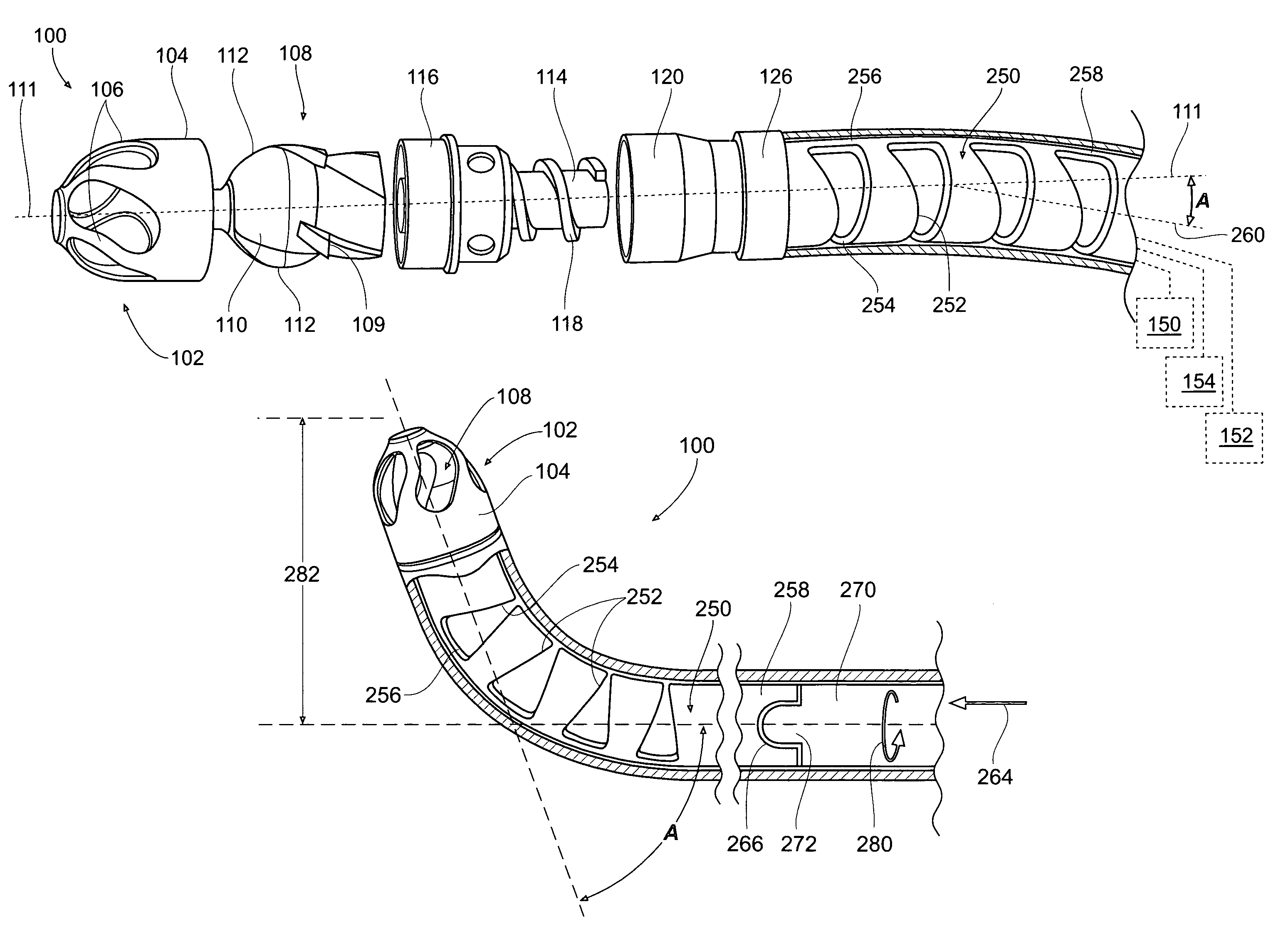
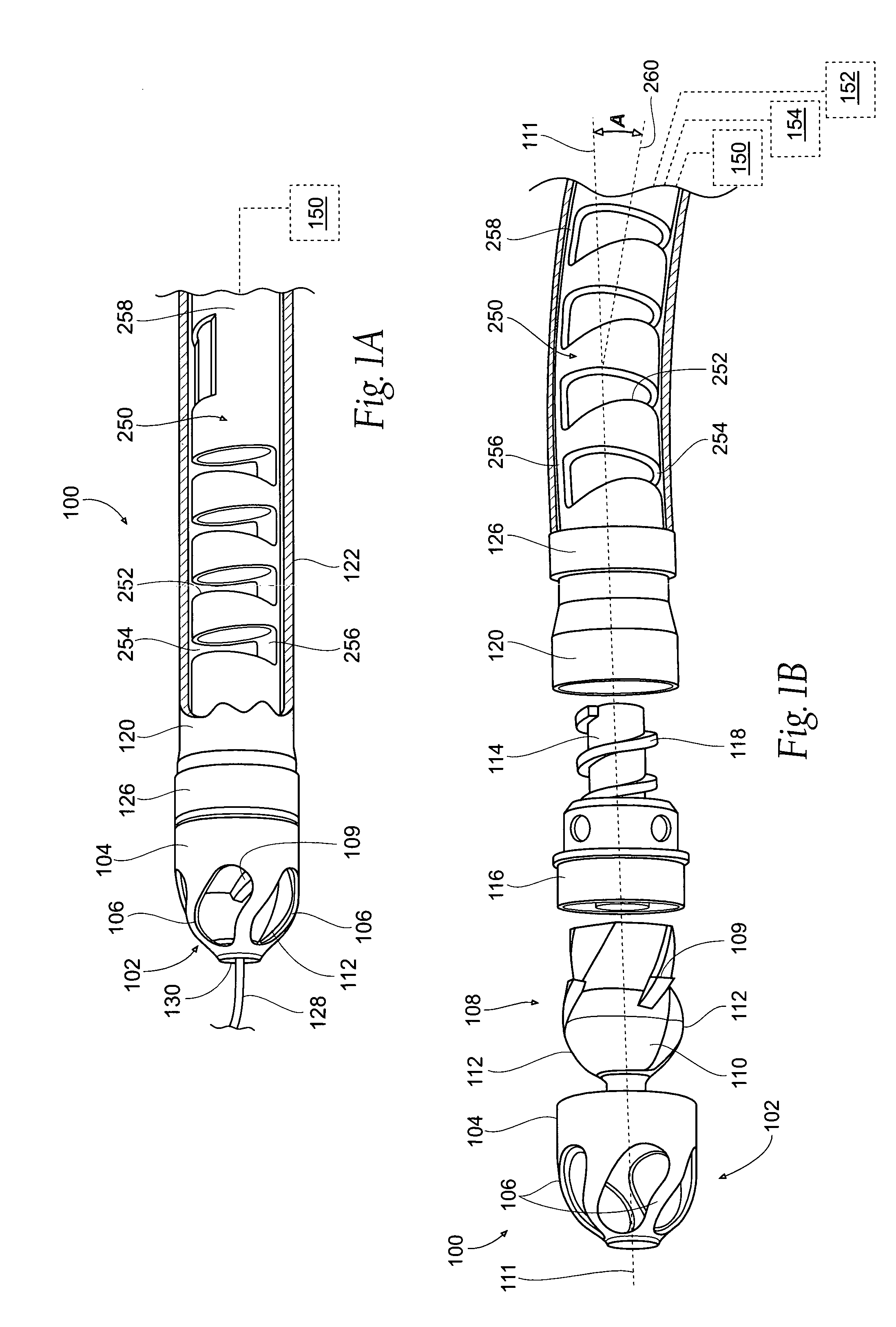
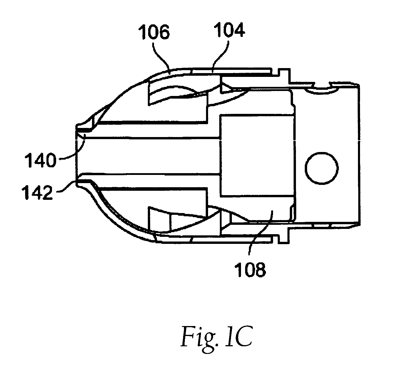
[0081]FIG. 1A illustrates an exemplary variation of a device 100 according to the present invention. As shown the device 100 includes a cutter assembly 102 affixed to a catheter or catheter body 120. The catheter body 120 can be a reinforced sheath (e.g., a polymeric material with a braid). It is noted that the cutter assembly shown in the figures exemplary purposes only. The scope of this disclosure includes the combination of the various embodiments, or single elements of various embodiments, where possible, as well as the combination of certain aspects of the various embodiments.

[0082]FIG. 1A s...


PUM


Abstract

The devices and methods generally relate to treatment of occluded body lumens. In particular, the present devices and method relate to removal of the occluding material from the blood vessels as well as other body lumens.

Description

RELATED APPLICATIONS[0001]This application claims the benefit of U.S. Provisional Patent Application Ser. No. 61 / 043,998, filed Apr. 10, 2008, and entitled “Atherectomy Devices and Methods,” which is incorporated herein by reference.[0002]This application is also a continuation-in-part of U.S. patent application Ser. No. 12 / 288,593, filed Oct. 22, 2008 now U.S. Pat. No. 8,070,762, and entitled “Atherectomy Devices and Methods,” which claims the benefit of U.S. Provisional Patent Application Ser. No. 60 / 981,735, filed Oct. 22, 2007, and entitled “Atherectomy Devices and Methods,” which are incorporated herein by reference.FIELD OF THE INVENTION[0003]The devices and methods described below generally relate to treatment of occluded body lumens. In particular, the present devices and method relate to improved devices for removal of the occluding material from the blood vessels as well as other body parts. Such devices include features for improved positioning within the vessel or body p...

Claims


Application Information

Patent Timeline
Patent Type & Authority Patents(United States)
IPC IPC(8): A61B17/22
CPCA61B17/320758A61B17/22A61B2017/00309A61B2017/22038A61B2017/22047A61B2017/22048A61B2017/22068A61B2017/22082A61B2017/320775A61M25/0147A61M25/0152A61M25/0138A61M25/0133A61M25/0136
Inventor TO, JOHN TESCUDERO, PAULDANEK, CHRISTOPHER JAMES
Owner ATHEROMED
Why Eureka
Try Eureka