
Synchronized audio/video decoding for network devices

a network device and audio/video technology, applied in the direction of synchronisation signal speed/phase control, selective content distribution, electrical apparatus, etc., can solve the problem that the echo effect detracts from the user's enjoyment of music being played in surround-sound audio decoding systems, network clients have no synchronization mechanism, and the delay between them gets gradually larger

Inactive Publication Date: 2012-08-07
SONY CORP +1
View PDF18 Cites 12 Cited by
  • Summary
  • Abstract
  • Description
  • Claims
  • Application Information

AI Technical Summary

Benefits of technology

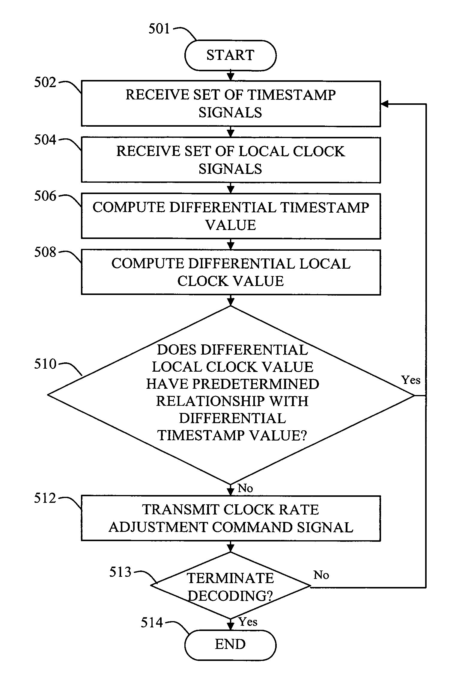
The patent text describes a method and system for synchronizing audio / video decoding in network devices. The system receives a set of timestamp signals and local clock signals from a network server, calculates a differential timestamp value and a differential local clock value, and checks if they have a predetermined relationship. If not, it adjusts the local system time clock to ensure that a subsequent differential local clock value will have the same relationship with the differential timestamp value. This allows for synchronized decoding of encoded data transmitted over the network. The technical effect of this invention is improved synchronization and accuracy in decoding network data.

Problems solved by technology

One drawback to conventional powerline networks is that network clients have no synchronization mechanism.
Thus, even when two network clients begin decoding an encoded data stream at the same time, a delay between them gets gradually larger over time because oscillators of the locks within the decoders operate independently.
If the audio delay becomes larger than 30 msec, an undesirable echo effect (i.e., the Haas Effect) occurs, resulting in the user hearing two audio tones.
Such an echo effect undesirably detracts from the user's enjoyment of music being played in surround-sound audio decoding systems.
Accordingly, conventional powerline networks will exhibit the undesirable Hass Effect within one hour of decoding audio data.

Method used


Image

  • Synchronized audio/video decoding for network devices
  • Synchronized audio/video decoding for network devices
  • Synchronized audio/video decoding for network devices

Examples


Embodiment Construction

[0023]The following description is not to be taken in a limiting sense, but is made merely for the purpose of describing the general principles of exemplary embodiments. The scope of the invention should be determined with reference to the claims.

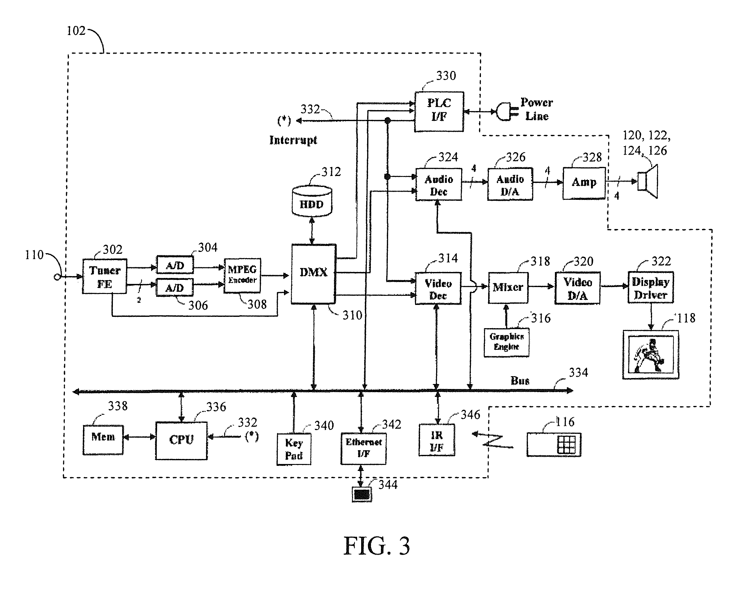
[0024]As disclosed herein, numerous embodiments allow decoders within a network to decode data in synchrony with other decoders within the network. Accordingly, numerous embodiments enable substantially synchronous operation by adjusting system time clocks (STCs) of decoders (i.e., local STCs) based upon timestamps output by a network server. Other embodiments enable substantially synchronous operation by adjusting the buffer occupancy of the decoders. By adjusting the STC and / or the buffer occupancy of decoders within the network, the decoders can decode encoded data substantially synchronously. When methods disclosed herein are performed for each decoder within the network, the decoders are substantially synchronized and a decoding delay ...


PUM


Abstract

A method of synchronizing decoders within a network to a server includes receiving a set of timestamps and local clock signals upon receiving the beacon interrupt signal, computing differential timestamp and local clock values based on values of timestamp and local clock signals, respectively, within the sets of timestamp and local clock signals, determining whether the differential local clock value has a predetermined relationship with the differential timestamp value, and transmitting a clock rate adjustment command signal to the decoder when differential local clock value does not have the predetermined relationship with the differential timestamp value. The clock rate adjustment command signal adjusts the local system time clock of the decoder such that a subsequent differential clock value will have the predetermined relationship with the differential timestamp value. When this method is performed for each decoder within the network, the decoders are substantially synchronized and the decoding delay can be kept below humanly perceptible levels.

Description

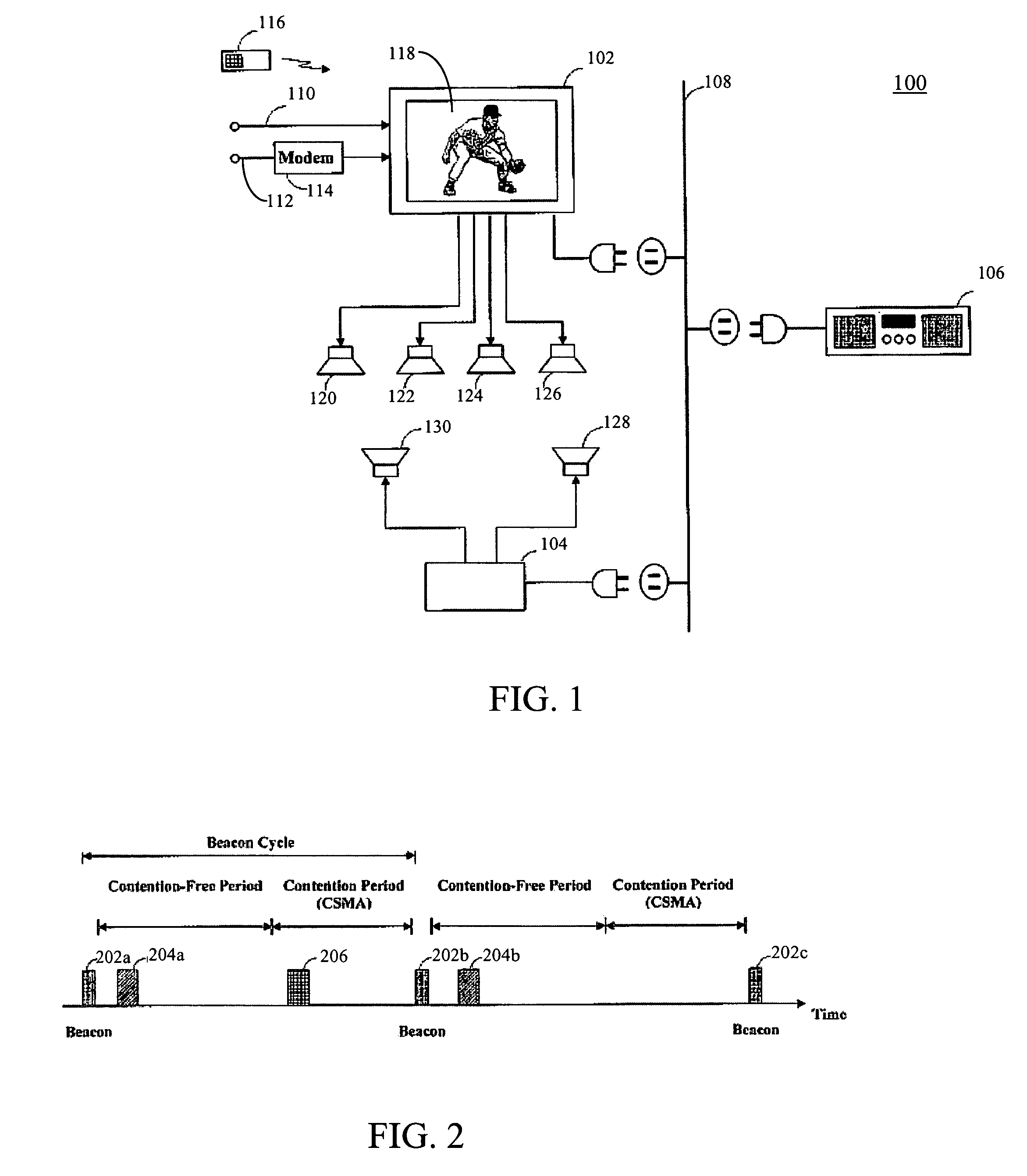
[0001]This application claims the benefit of U.S. Provisional Application No. 60 / 671,223, filed Apr. 13, 2005, which is incorporated in its entirety herein by reference.BACKGROUND[0002]1. Field of Invention[0003]Embodiments described herein relate generally to synchronized audio / video decoding for network devices.[0004]2. Discussion of the Related Art[0005]Various schemes have been proposed for distributing media information (e.g., video data, audio data, etc.) along communication links within a media network. One type media network is a powerline network that essentially uses the AC electrical wiring of a house (i.e., the powerline) as a transmission medium. Accordingly, within a powerline network, a network server can transmit media information (i.e., one or more encoded data streams) to one or more network clients that are “plugged in” to AC electrical outlets within a house. The network clients receive and decode the encoded data stream and output the decoded data stream in an a...

Claims


Application Information

Patent Timeline
Patent Type & Authority Patents(United States)
IPC IPC(8): H04J3/06H04N19/00H04N19/423H04N19/70
CPCH04N21/2368H04N21/43615H04N21/4341H04N21/4305H04J3/06H04L7/10
Inventor IWAMURA, RYUICHI
Owner SONY CORP
Learn More