
Lossless video data compressor with very high data rate

a video data compressor and data rate technology, applied in computing, instruments, electrical equipment, etc., can solve the problems of lossless entire compression and decompression cycle, reduce the dynamic range of data, etc., and achieve the effect of no loss of information or image quality

Active Publication Date: 2012-08-07
COGNITECH
View PDF13 Cites 5 Cited by
  • Summary
  • Abstract
  • Description
  • Claims
  • Application Information

AI Technical Summary

Benefits of technology

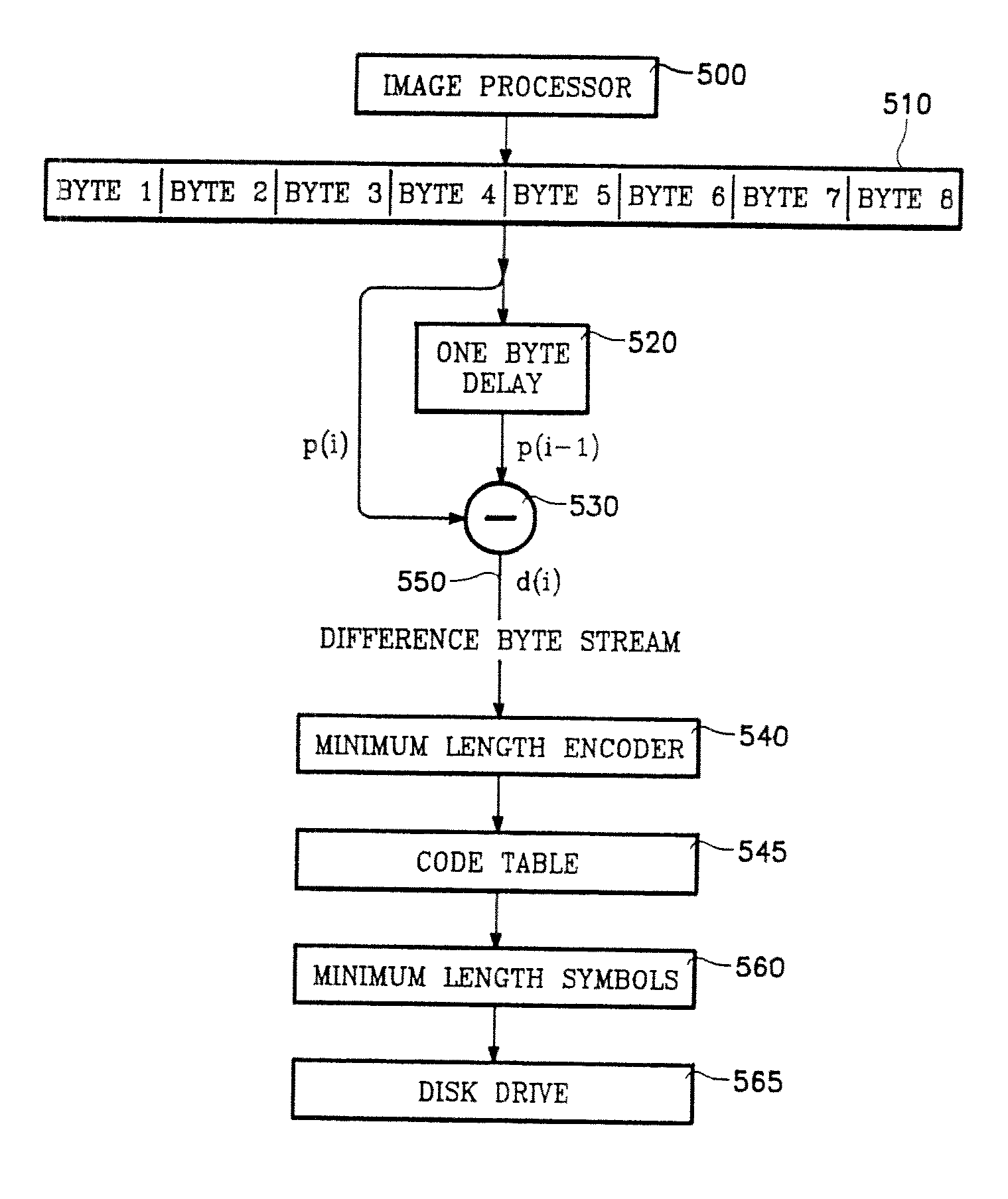
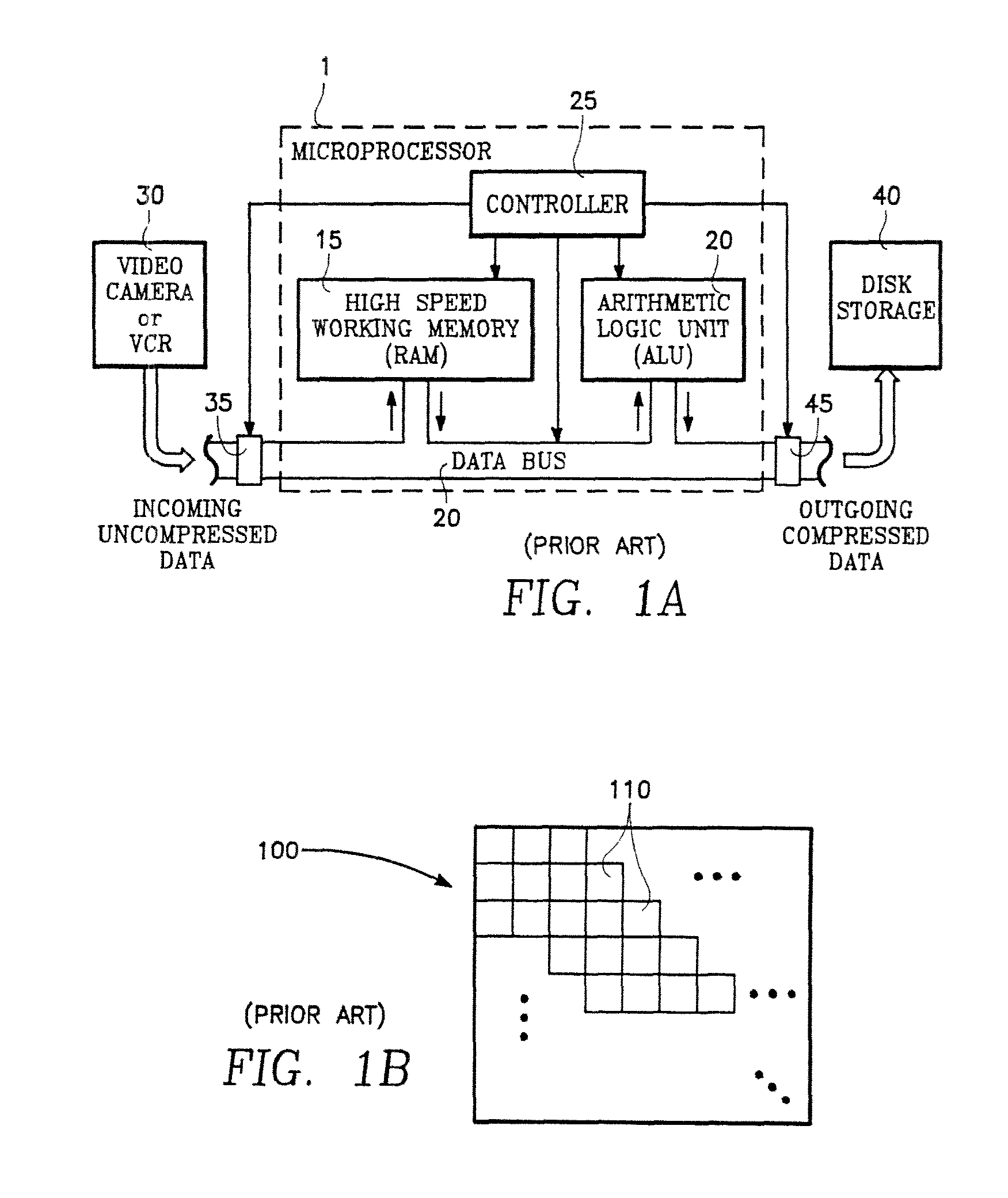
[0009]In the video compression process of the invention, there is no loss of image quality upon de-compression, while the compression ratio is very high (a compression ratio of two or more) and, significantly, the compression process operates at very high incoming video data rates in real time. This is achieved by a discovery of the invention in which lossless video compression is achieve using a minimal number or arithmetic operations for each pixel. The entire video frame may compressed as a whole or it may be compressed block-by-block. The compression process compresses Incoming video data in real time without requiring data buffering and provides the required balance or compensation between the high incoming video data rate of a video camera and the lower write speed of a disk storage device.
[0011]The de-compression process begins by playing back the data recorded on the disk. The playback process is followed by extracting the code table of the current frame using this table to convert the minimum length symbols of the current frame to the corresponding difference pixel bytes. Then, the difference pixel bytes are converted to pixel bytes by adding the previously computed pixel byte to the current difference byte, to generate a stream of pixel bytes from the difference bytes. The stream of pixel bytes constitute the de-compressed video data. The computation of the pixel bytes from the difference bytes inherently restores any information seemingly lost by the discarding of carry bits in the foregoing compression process.
[0012]The recovery of the difference bytes from the minimum length symbols in accordance with the minimum length coding table is an exact process without error. The recovery of the pixel bytes from the difference bytes by the foregoing addition step is an exact process and produces the pixel bytes without error or loss. Therefore, the entire compression and decompression cycle is lossless. However, the compression process achieves a compression ratio of two or more. As a result, the compression process is sufficient to record real time (30 frame per second) video data onto a single disk with no loss of information or image quality.

Problems solved by technology

This step reduces the dynamic range of the data.
Therefore, the entire compression and decompression cycle is lossless.

Method used


Image

  • Lossless video data compressor with very high data rate
  • Lossless video data compressor with very high data rate
  • Lossless video data compressor with very high data rate

Examples


Embodiment Construction

Compression:

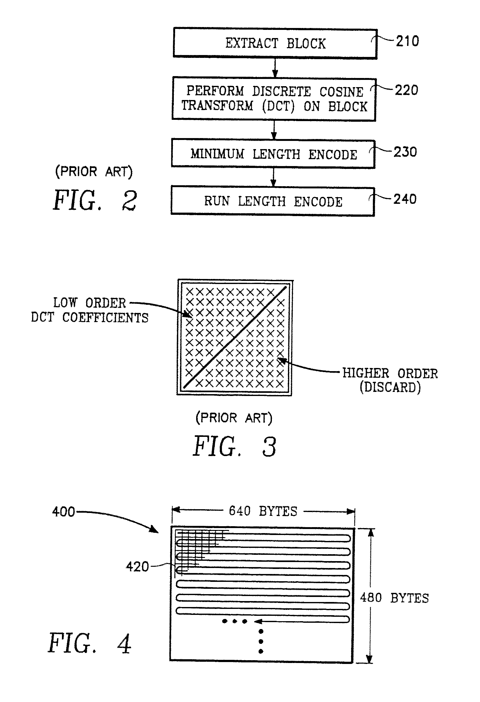
[0027]Referring to FIG. 4, each individual frame 400 is a two-dimensional array of picture elements (“pixels”) 420, the picture elements 420 being arranged in rows and columns of pixels. Following analog-to-digital conversion of the video frame, each pixel is represented by a byte, such as an 8-bit byte, so that the digital representation of a video frame is a two dimensional array of 8-bit bytes corresponding to the array of pixels 420 of FIG. 4, for example. Such bytes may be referred to as “video pixel bytes”. Each pixel byte represents the intensity of the corresponding pixel. Hereinafter, the term “video frame” shall refer to the array of video pixel bytes. If the video frame was derived from an NTSC video signal, then the video frame has 640 columns and 480 rows of video pixel bytes corresponding to the array of pixels 420 of FIG. 4. Hereinafter, the pixels 420 of FIG. 4 shall be considered herein as synonymous with video pixel bytes. If the video frame represents ...


PUM


Abstract

Lossless video data compression is performed in real time at the data rate of incoming real time video data in a process employing a minimum number of computational steps for each video pixel. A first step is to convert each pixel 8-bit byte to a difference byte representing the difference between the pixel and its immediate predecessor in a serialized stream of the pixel bytes. Thus, each 8-bit pixel byte is subtracted from its predecessor. This step reduces the dynamic range of the data. A next step is to discard any carry bits generated in the subtraction process of two's complement arithmetic. This reduces the data by a factor of two. Finally, the 8-bit difference pixel bytes thus produced are subject to a maximum entropy encoding process. Such a maximum entropy encoding process may be referred to as a minimum length encoding process. One example is Huffman encoding. In such an encoding process, a code table for the entire video frame is constructed, in which a set of minimum length symbols are correlated to the set of difference pixel bytes comprising the video frame, the more frequently occurring bytes being assigned to the shorter minimum length symbols. This code table is then employed to convert the all of the difference pixel bytes of the entire video frame to minimum length symbols.

Description

CROSS-REFERENCE TO RELATED APPLICATIONS[0001]This application is a continuation of application Ser. No. 10 / 670,415 filed Sep. 24, 2003 now U.S. Pat. No. 7,548,658, the disclosure of which is incorporated by reference.BACKGROUND OF THE INVENTION[0002]The invention concerns the processing of video data for recording on a disk. Video data typically consists of a succession of video frames, each frame consisting of (in the case of NTSC video) 640 columns and 480 rows of picture elements (pixels). Typically, each pixel consists of an eight-bit byte representing the intensity value of the pixel. Video data typically is generated at the rate of 30 frames per second (in the case of NTSC video). In the case of color video, each image consists of three different channels, one channel for each of three primary colors (e.g., red, green and blue). From the foregoing, the data rate of digital color video data is calculated to be about 27 megabytes per second.[0003]Storing video data as it is gene...

Claims


Application Information

Patent Timeline
Patent Type & Authority Patents(United States)
IPC IPC(8): G06K9/46
CPCH04N19/593H04N19/182H04N19/91H04N19/13H04N19/136H04N19/176
Inventor RUDIN, LEONID I.YU, PING
Owner COGNITECH
Learn More