Hydraulic energy recovery system

Inactive Publication Date: 2012-08-14
POCLAIN HYDRAULICS IND
View PDF6 Cites 3 Cited by
  • Summary
  • Abstract
  • Description
  • Claims
  • Application Information

AI Technical Summary

Problems solved by technology

Unfortunately, the shape and the size of such a low-pressure accumulator can pose compactness problems.
In addition, if the cubic capacity of the motor is fixed, it is not possible to adjust the hydrostatic braking torque or the drive torque to match real needs.
As a result, the possibilities of storing fluid during an energy recovery phase and the possibilities of delivering drive assistance during an energy delivery phase are relatively limited, which naturally adversely affects the efficiency of the circuit and thus the overall performance thereof.
In other w

Method used


Image

  • Hydraulic energy recovery system
  • Hydraulic energy recovery system
  • Hydraulic energy recovery system

Examples


Embodiment Construction

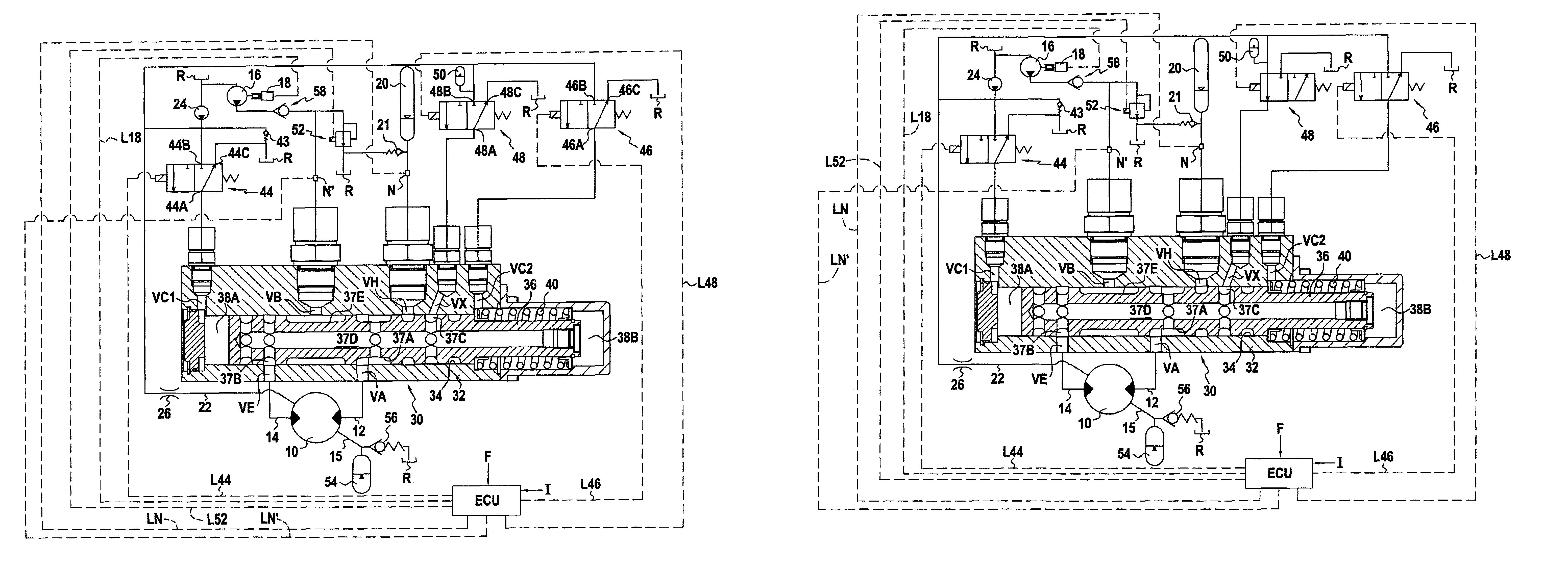
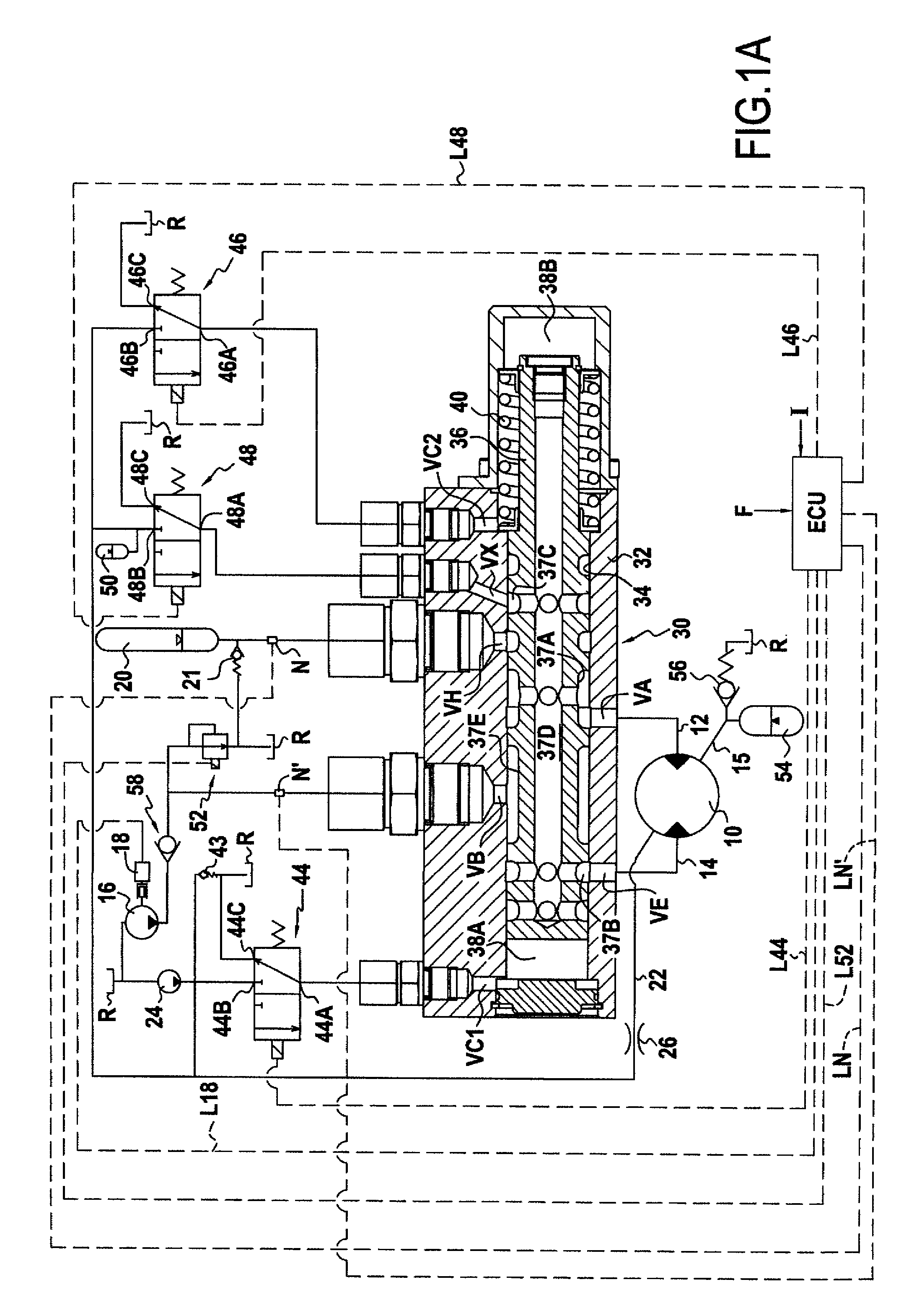
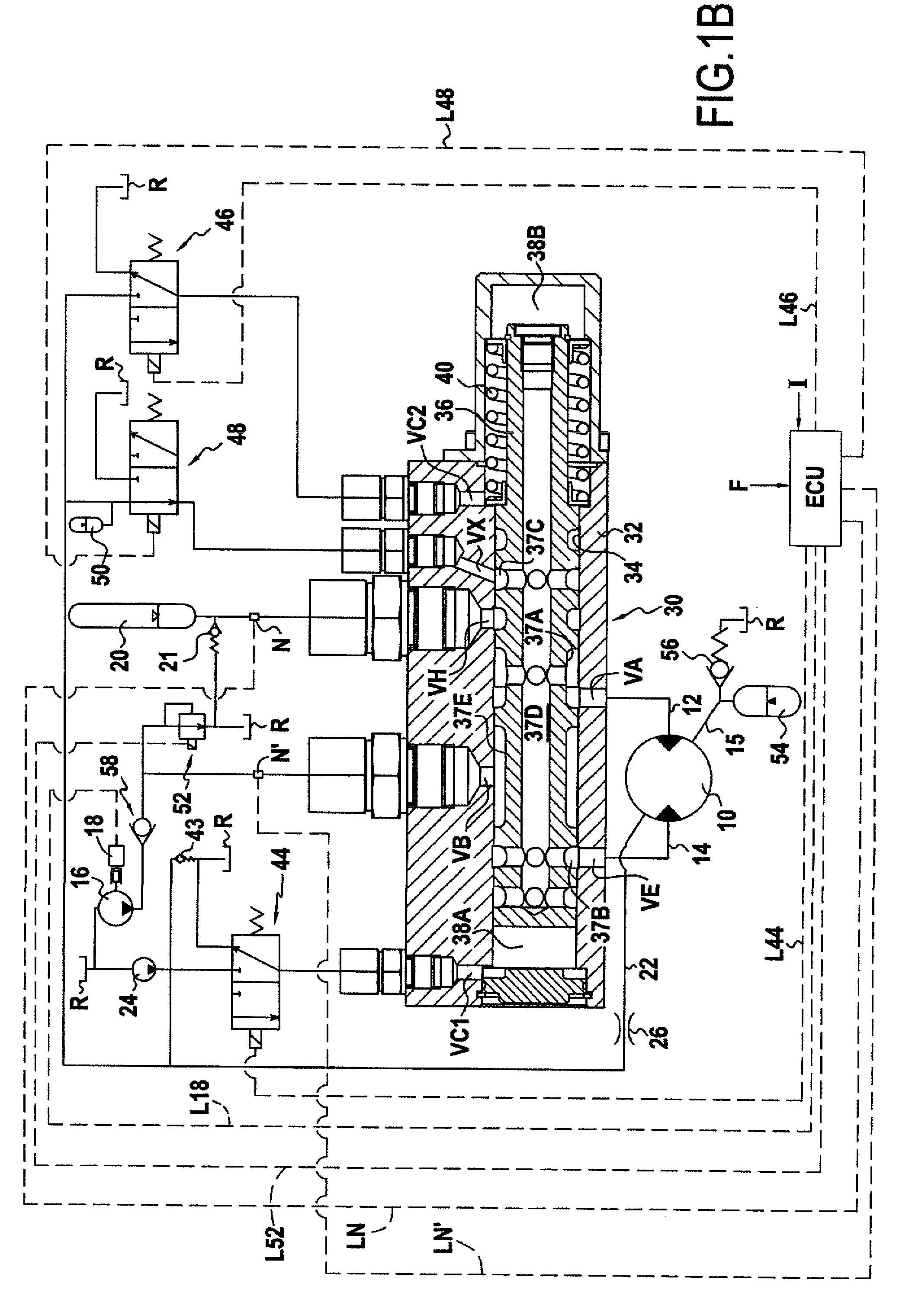
[0032]The circuit shown in FIGS. 1A to 1E includes a hydraulic motor 10 with two main ducts, respectively 12 and 14, for feeding fluid to said motor and for discharging fluid therefrom. It also includes a low-pressure fluid source 16 formed by a high-flow-rate booster pump, which pumps the fluid from a pressure-free reservoir R (a reservoir at atmospheric pressure). Said pump is chosen to be suitable for delivering a flow rate of fluid that is sufficient to feed fluid to the hydraulic motor while said motor is at maximum speed, in the energy recovery configuration. If a plurality of motors are present in the circuit, the same high-flow-rate booster pump is advantageously used, which booster pump is dimensioned to deliver the flow rate of fluid that is sufficient to feed the various motors without cavitation when said motors are at maximum speed in this configuration.

[0033]The pump 16 is driven by an engine that can be the conventional propulsion engine of the vehicle. Means are prov...


PUM


Abstract

A circuit having at least one hydraulic motor, two main ducts for feeding or discharging the at least one motor, a low-pressure fluid source, and a high-pressure accumulator forming a high-pressure fluid source. The circuit is suitable for operating in an energy recovery mode in which the feed main duct is connected to the low-pressure fluid source and the discharge main duct is connected to the high-pressure accumulator, and in an energy delivery mode in which the connections are inverted. The low-pressure fluid source has a high-flow-rate booster pump suitable for delivering a flow-rate of fluid that is sufficient to feed fluid to the at least one hydraulic motor while the motor is at maximum speed in energy recovery mode, and an adjustable pressure limiter suitable for being controlled so as to cause the pressure of the fluid at the outlet of the low-pressure fluid source to vary.

Description

BACKGROUND OF THE INVENTION[0001]The present invention relates to a hydraulic circuit for recovering energy, which circuit comprises at least one hydraulic motor, two main ducts for feeding or discharging said at least one motor, a low-pressure fluid source, and a high-pressure accumulator forming a high-pressure fluid source, the circuit being suitable for operating in energy recovery mode in which the feed main duct is connected to the low-pressure fluid source and the discharge main duct is connected to the high-pressure accumulator, and in energy delivery mode in which the feed main duct is connected to the high-pressure accumulator and the discharge main duct is connected to the low-pressure fluid source.[0002]It is known that such circuits can be fitted to vehicles for the purpose of limiting energy consumption. Such vehicles are “hybrid” vehicles, each such vehicle having a conventional propulsion engine (e.g. of the internal combustion engine type) and a circuit of the above...

Claims


Application Information

Patent Timeline
IPC IPC(8): F16H61/40B60K5/12F16H61/4026F16H61/4043F16H61/4061F16H61/4096F16H61/4139F16H61/4157F16H61/42F16H61/423
CPCB60K6/12F16H61/4026F16H61/4043F16H61/4061F16H61/4139F16H61/4148F16H61/4157F16H61/4096F16H61/423Y02T10/6208Y02T10/76Y02T10/62
Inventor HEREN, JEANLEMAIRE, GILLES
Owner POCLAIN HYDRAULICS IND
Why Eureka
Try Eureka