Method for Controlling Rotation Speed

Active Publication Date: 2008-09-11
VOLVO CONSTR EQUIP
View PDF10 Cites 13 Cited by
  • Summary
  • Abstract
  • Description
  • Claims
  • Application Information

AI Technical Summary

Benefits of technology

[0021]According to a preferred embodiment, when the first control model is utilized, the rotational speed of the rotating element is controlled in such a

Problems solved by technology

A basic problem for all vehicles that are driven with several points of contact with the ground is how the propulsive force is distributed.
This would, however, not work when cornering.
The slippage cannot, however, be controlled.
The disadvantage of a differential lock is that the speed difference when cornering manifests itself as sl

Method used


Image

  • Method for Controlling Rotation Speed
  • Method for Controlling Rotation Speed
  • Method for Controlling Rotation Speed

Examples


Embodiment Construction

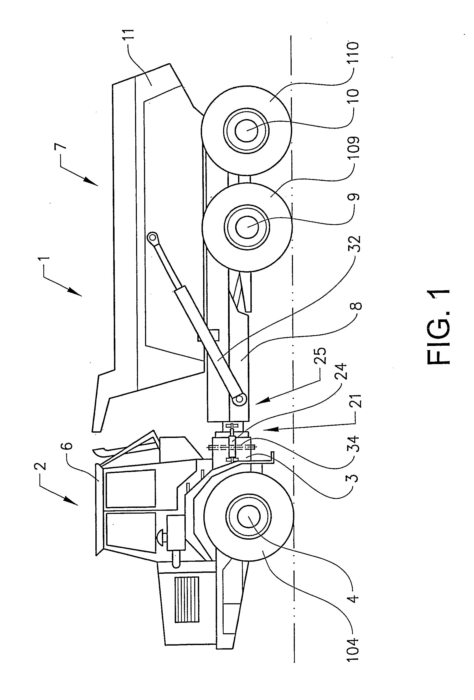
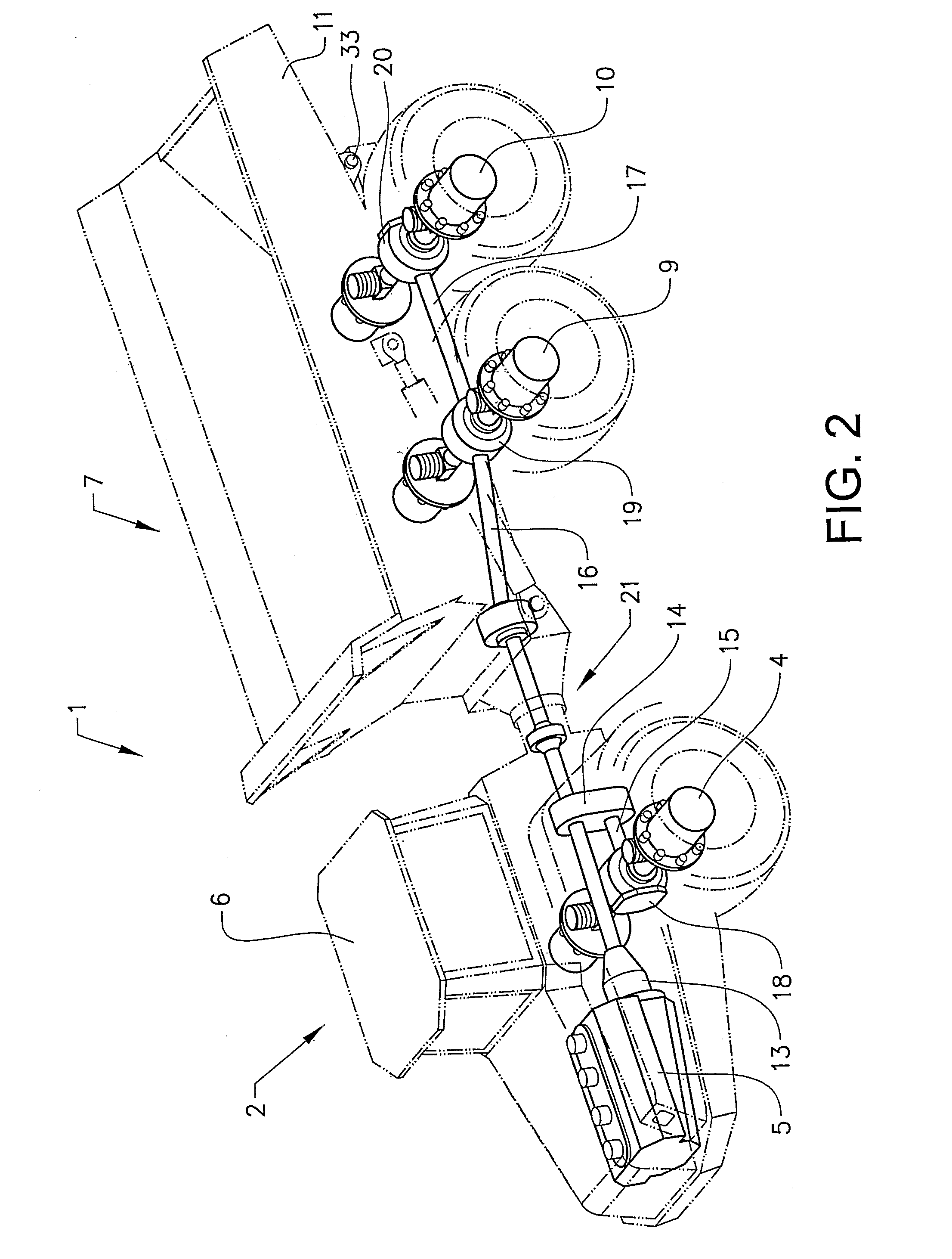
[0035]FIG. 1 shows an articulated hauler 1 in a side view. The articulated hauler comprises a front vehicle section 2 comprising a front frame 3, a front axle 4 and a cab 6 for a driver. The articulated hauler 1 also comprises a rear vehicle section 7 comprising a rear frame 8, a front axle 9, a rear axle 10 and a tipping load container, or platform, 11.

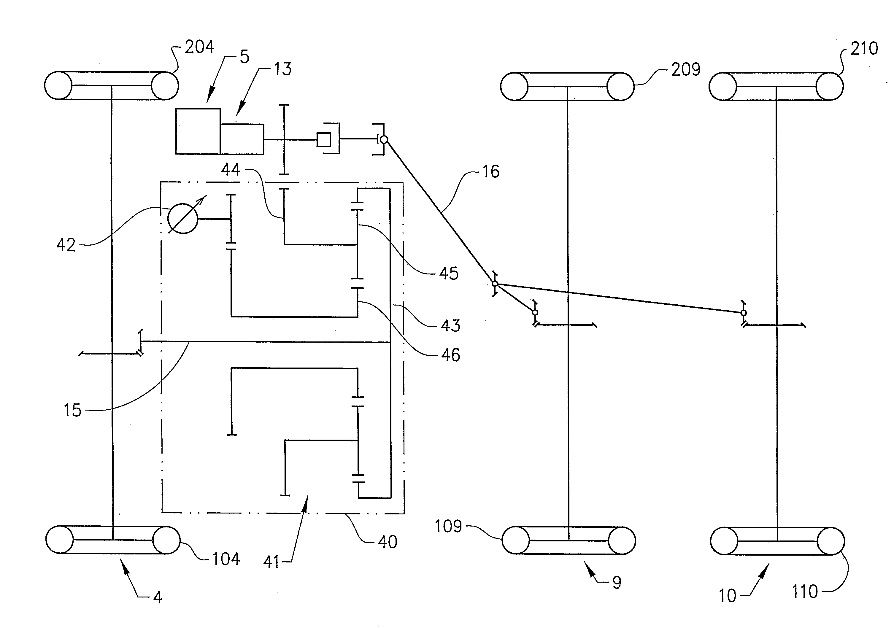
[0036]The front and rear axles 9,10 in the rear vehicle section 7 are connected to the rear frame 8 via a bogie arrangement 12, see FIG. 3, and will be referred to below as the front bogie axle 9 and rear bogie axle 10 respectively.

[0037]The front axle 4, the front bogie axle 9 and the rear bogie axle 10 each comprise a left ground-engaging element 104,109,110 and a right ground-engaging element 204,209,210 in the form of wheels.

[0038]The front frame 3 is connected to the rear frame 8 via a first pivot joint 21 that allows' the front axle 3 and the rear axle 8 to pivot relative to each other around a vertical pin 34 for steering (tur...


PUM


Abstract

A method for controlling the rotational speed of at least one rotating element in a vehicle's drive line is provided. A first control model and a second control model are defined. The first control model calculates a permitted slippage of at least one of the vehicle's ground-engaging elements at its point of contact with the ground, which ground-engaging element is driven via the rotating element. The second control model calculates a torque delivered to the said ground-engaging element. The result of one of the said control models is utilized for controlling the rotational speed of the rotating element.

Description

BACKGROUND AND SUMMARY[0001]The present invention relates to a method for controlling the rotational speed of a rotating element in the drive line of a vehicle.[0002]By the term “rotating element” is meant a shaft, such as a longitudinal drive shaft (for example universal drive shaft) or transverse drive shaft (that is wheel axle) or other element that is arranged to rotate and is comprised in the drive line for the transmission of power.[0003]By the term “drive line” is meant the whole power-transmission system from the vehicle's motor to its ground-engaging elements. The drive line thus comprises clutch, gearbox (and any distribution gearbox), universal drive shaft (or universal drive shafts), transverse drive shafts, etc. Hydraulic, electrical and other driving systems are also included within the term “drive line”.[0004]The term “ground-engaging elements” includes wheels, caterpillar tracks, etc.[0005]The invention can be implemented on wheeled vehicles, tracked vehicles and veh...

Claims


Application Information

Patent Timeline
IPC IPC(8): B60K28/16
CPCB60K6/12B60K28/16B60L2240/486B60W2710/1011B60W2710/1038Y10T477/70F16H47/04Y02T10/6208B60L2200/26Y10T477/78Y10T477/755B60Y2200/14Y02T10/62B60W2050/0031
Inventor OLSSON, KARL ERIK
Owner VOLVO CONSTR EQUIP
Why Eureka
Try Eureka