Release assembly for crossbow

a technology of release assembly and crossbow, which is applied in the field of crossbows, can solve the problems of reducing the accuracy of the shot, increasing the difficulty of carrying and operating quickly, and increasing the difficulty of crossbows to be released. it can achieve the effect of enhancing the force/drawing characteristics of the crossbow

Active Publication Date: 2012-08-14
PRECISION SHOOTING EQUIP
View PDF36 Cites 66 Cited by
  • Summary
  • Abstract
  • Description
  • Claims
  • Application Information

AI Technical Summary

Benefits of technology

[0021]Briefly described, and in accordance with a preferred embodiment thereof, the present invention relates to a crossbow which includes certain components that are conventionally included in a crossbow, including a rigid riser (or “prod”), and first and second flexible limbs coupled to opposing end portions of the riser. A bowstring extends between the limb tips of the first and second limbs for propelling an arrow, or “bolt”. Preferably, first and second pulleys / cams are rotatably supported at the limb tips of the first and second limbs, respectively, and the bowstring extends between such first and second pulleys. Preferably, the crossbow further includes power cables engaged with the first and second pulleys / cams to enhance the force / draw characteristics of the crossbow.
[0026]As noted above, the components of the bowstring retractor (with the exception of the crank arm) are contained within the aforementioned upper housing located proximate the second end of the elongated frame. The same upper housing also preferably serves to aid in positioning the bowstring release into its proper fully-drawn position. As the bowstring release approaches its fully-drawn position, it is pulled into the upper housing proximate the trigger, wherein the actuating lever of the bowstring release is disposed proximate to the trigger. In the preferred embodiment, the upper surface of the elongated frame has a guide channel formed therein; this guide channel extends from at least the rest position of the bowstring to the upper housing. The guide channel receives the base of the bowstring release, and assists in guiding the bowstring release along the elongated frame, and into the upper housing, as the bowstring release is retracted.
[0027]In the preferred embodiment, the bowstring release includes a cocking bar for cocking the trigger assembly as the bowstring release is retracted into the upper housing. Assuming, for example, that the trigger assembly includes a spring-biased hammer, then the cocking bar can automatically reset the hammer into a cocked position as the bowstring release is retracted into the upper housing. Ideally, the cocking bar is pivotally mounted to the bowstring release; the cocking bar is prevented from pivoting when the bowstring is being retracted. After an arrow is fired, the cocking bar is permitted to pivot to avoid any interference with the trigger assembly, or the hammer thereof, when the bowstring release is pulled away from the upper housing. Preferably, the end of the retractor rope that is coupled to the bowstring release is engaged with the cocking bar to prevent the cocking bar from pivoting when the rope is taut, while permitting the cocking bar to pivot when the rope is slack.
[0029]In practicing such method, the retractor rope is preferably pulled by rotatably supporting a rope spool proximate the second end of the elongated frame, engaging one end of the rope with the rope spool, and rotating the spool to wind the rope around the spool, thereby pulling the bowstring release, and the bowstring engaged thereby, toward the drawn position. Preferably, such method includes coupling at least one spool gear to the spool, and engaging a pawl with the spool gear for permitting rotation of the spool in a first direction, and for selectively preventing rotation of the spool in a second, opposing direction.

Problems solved by technology

This often results in an excessive pull force which the user must exert upon the trigger of the crossbow to fire the arrow, which in turn decreases the accuracy of the shot.
Crossbows can be relatively heavy, making them more difficult to carry and operate quickly.
Complex trigger mechanisms and bowstring retraction systems often contribute to such excessive weight.
Again, this requirement often results in the need for the user to exert excessive finger pull pressure on the trigger to release the bowstring, particularly when the crossbow has a relatively high draw weight.
The cocking mechanism disclosed by Luoma does not permit rapid retraction of the bowstring, and the drawback rod does not appear to be sufficiently sound to bear significant draw weights while ensuring an accurate shot.
In addition, the requirement for loading the arrow upon a rail, and the resulting frictional forces between the arrow and the rail during firing, limit the arrow speed that can be produced by such a crossbow.

Method used


Image

  • Release assembly for crossbow
  • Release assembly for crossbow
  • Release assembly for crossbow

Examples


Embodiment Construction

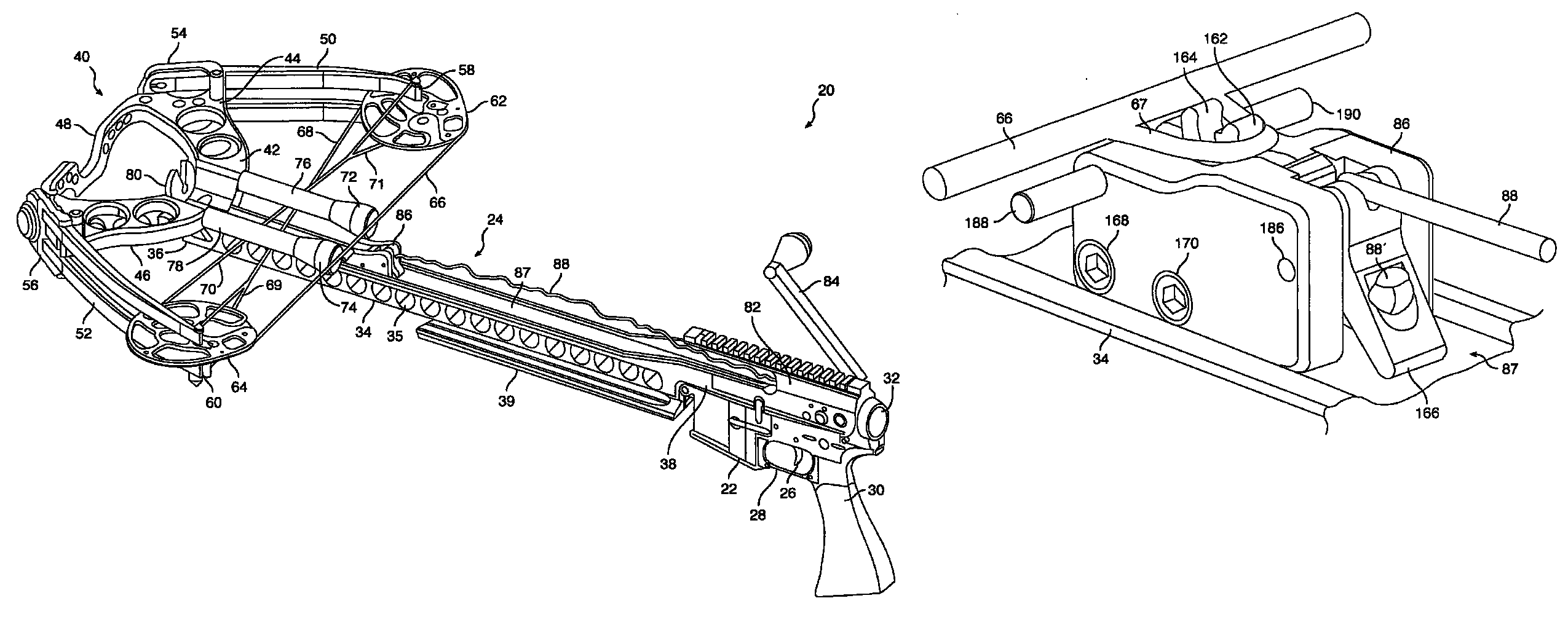
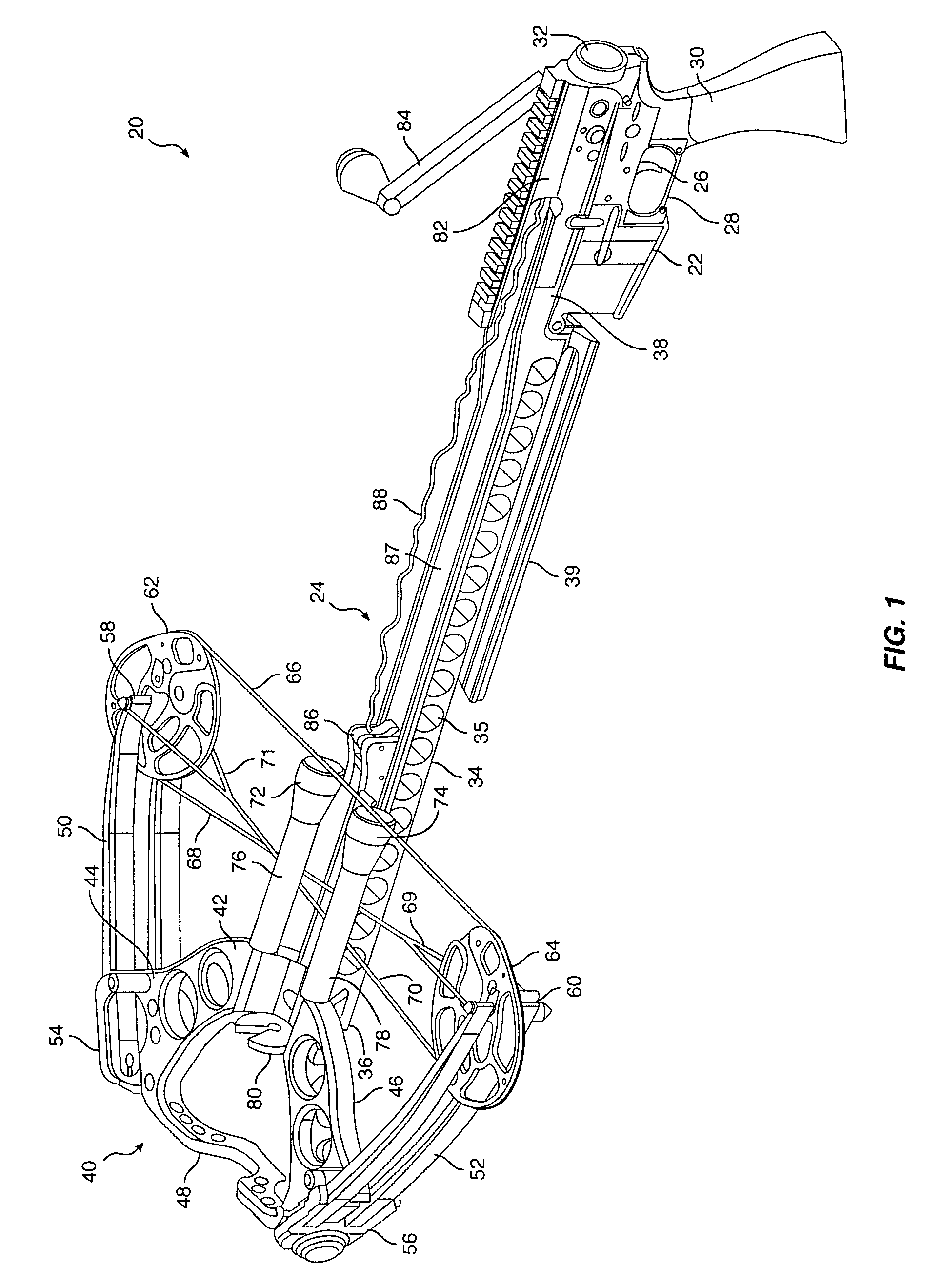
[0055]FIG. 1 shows a crossbow, designated generally by reference numeral 20, and including the nodular lower receiver 22 of an AR-15 style rifle attached to crossbow accessory 24. While the described embodiment uses an AR-15 style lower receiver 22, those skilled in the art will appreciate that the present invention can also be practiced by using lower receivers of other models of rifles. In addition, while the described embodiment of the present invention is a crossbow accessory for an existing lower receiver already owned by a user, those skilled in the art will appreciate that a manufacturer could, if desired, incorporate a trigger and hammer assembly into the described crossbow accessory 24 to provide an integral crossbow while practicing the inventive features described and claimed herein.

[0056]As is known to gun enthusiasts, lower receiver 22 includes a finger trigger 26 which extends downwardly from the housing of lower receiver 22. A trigger guard 28 may also be included. A ...


PUM


Abstract

A crossbow includes an elongated frame coupled to a riser at a first end thereof. The riser supports a pair of flexible limbs, and a bowstring extends between such limbs. A movable bowstring release is used both to retract the bowstring into a drawn position, and to release the bowstring under the operation of a trigger assembly. The bowstring release is initially positioned near the bowstring at rest, and a bowstring hook is engaged therewith. A bowstring retractor includes a retractor rope secured to the bowstring release for retracting the bowstring. An upper housing is secured to the second end of the elongated frame, and supports a rope spool used to wind the retractor rope. The bowstring release is retracted into the upper housing proximate a trigger assembly for selectively releasing the bowstring when a user pulls a trigger.

Description

CROSS-REFERENCE TO RELATED APPLICATIONS[0001]The present application is related to a co-pending application Ser. No. 12 / 350,106, filed concurrently herewith, and entitled “Crossbow Accessory for Lower Receiver of Rifle and Related Method”, assigned to the assignee of the present application.[0002]The present application is related to a co-pending application Ser. No. 12 / 350,131, filed concurrently herewith, and entitled “Compact Winding Mechanism for Crossbow”, assigned to the assignee of the present application.BACKGROUND OF THE INVENTION[0003]1. Field of the Invention[0004]The present invention relates generally to crossbows, and more specifically, to a mechanism for releasing the bowstring of a crossbow to fire an arrow.[0005]2. Description of the Related Art[0006]Crossbows have also long been known in the archery field for use in hunting game. Crossbows have higher draw weights than conventional archery bows and fire arrows (or “bolts”) with greater speeds. As a result, crossbow...

Claims


Application Information

Patent Timeline
Patent Type & Authority Patents(United States)
IPC IPC(8): F41B5/12F41B5/18
CPCF41A11/02F41A19/12F41B5/123F41B5/1469F41C23/00F41B5/12
Inventor KRONENGOLD, DAVID H.RASOR, ALLEN C.HANSEN, KEVIN
Owner PRECISION SHOOTING EQUIP
Why Eureka
Try Eureka