
Linear compressor

a linear compressor and construction technology, applied in the direction of pump parameters, piston pumps, pump components, etc., can solve the problems of increasing manufacturing and shipping costs, unfavorable vibration control, and unfavorable vibration control of this type of compressor

Active Publication Date: 2012-08-14
EMBRACO IND DE COMPRESSORES E SOLUCOES EM REFRIGERACAO LTDA
View PDF18 Cites 66 Cited by
  • Summary
  • Abstract
  • Description
  • Claims
  • Application Information

AI Technical Summary

Benefits of technology

[0017]As a function of the drawbacks commented above and other disadvantages of the known constructive solutions, it is one of the objects of the invention to provide a linear compressor comprising a reference assembly and a resonant assembly, which are lodged in the interior of a shell, and presenting a mounting arrangement of the elements of the resonant assembly which allows to practically annul the levels of the vibrations transmitted from the reference and resonant assemblies to the compressor shell.
[0019]Another object of the present invention is to provide a linear compressor, as cited above and whose construction permits a substantial reduction of the dimensions of the compressor shell and also of the overall weight of the latter.

Problems solved by technology

This vibration is undesirable for this type of compressor, especially when used in residential refrigeration systems.
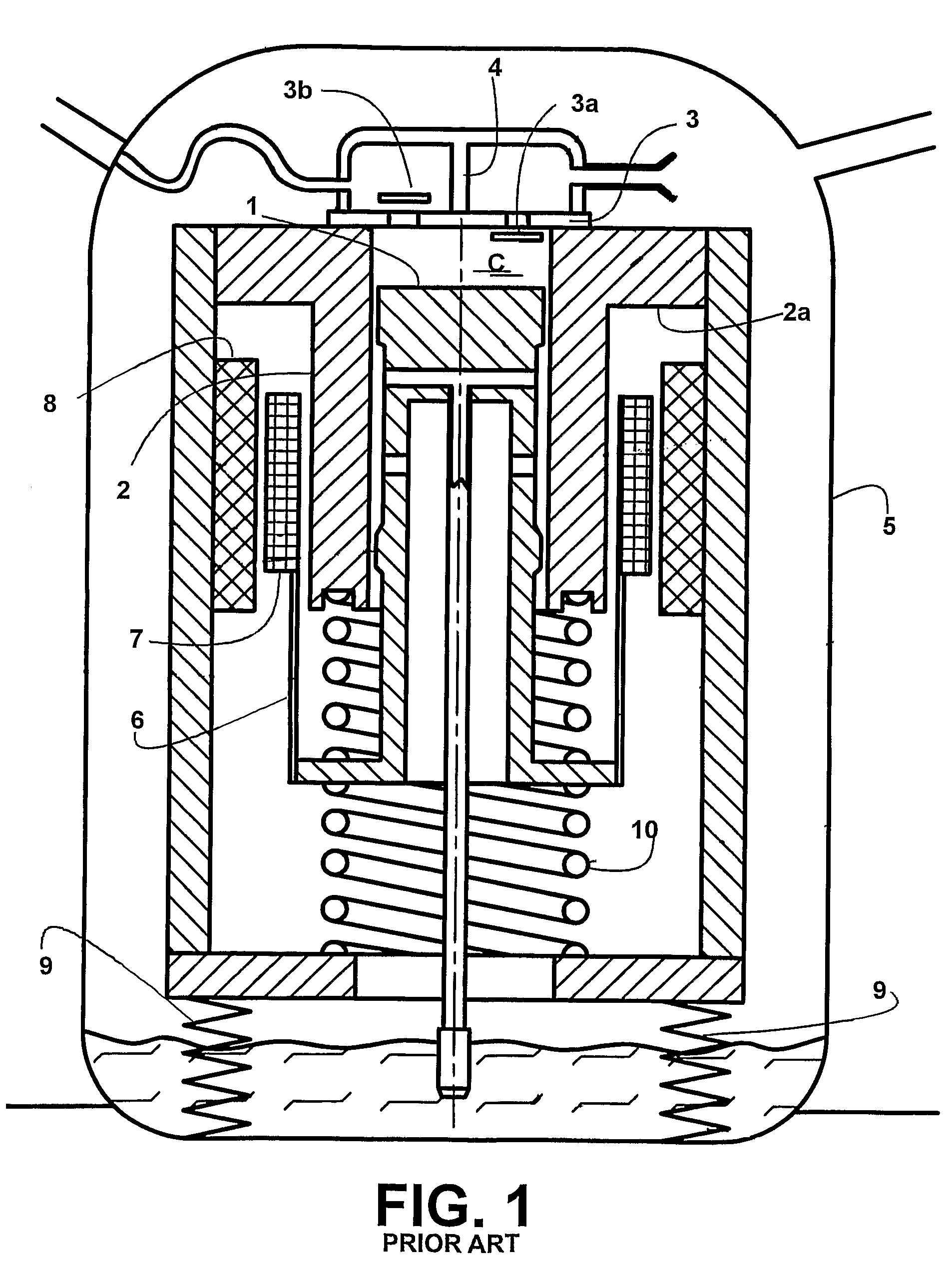
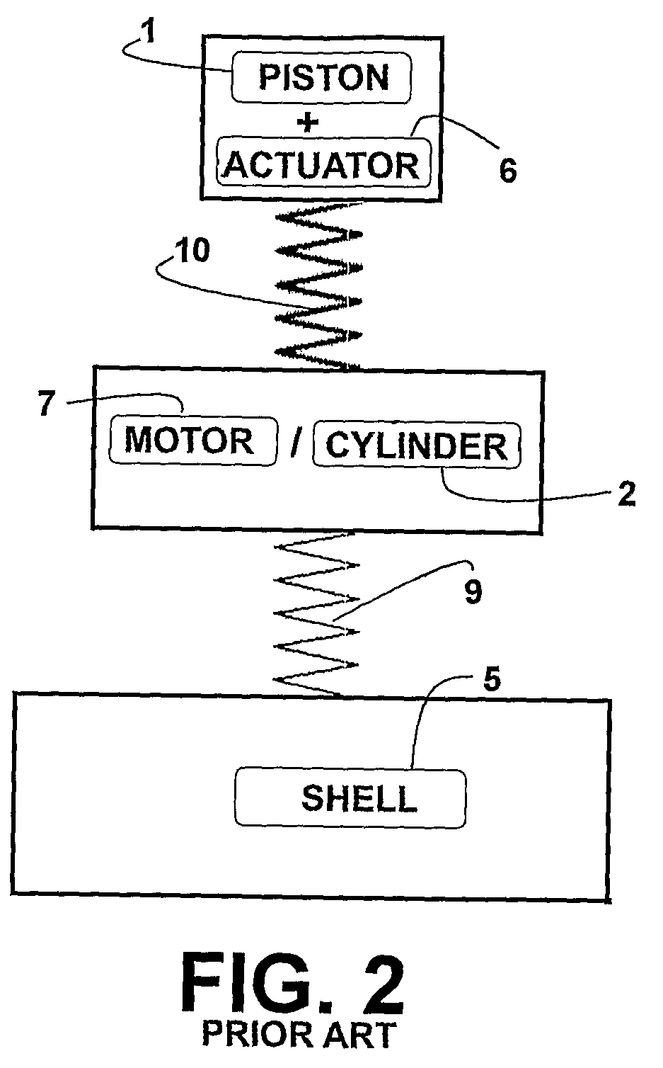
However, in these prior art solutions, the whole mass of the resonant assembly is displaced as a single body in one and in an opposite direction during the reciprocating displacement of the piston.
Considering the dimensional limitations of these compressors, the known solutions, in which the elements of the resonant assembly are defined as a single body, do not allow the vibration control means to be dimensioned to practically annul the vibrations transmitted to the compressor shell.
As a consequence of the need for maintaining the vibration control means in the prior art solutions, these known linear compressors require larger shell dimensions for mounting said vibration control means, which leads to the necessity of a larger physical space to install the compressor and to a heavier compressor.
These drawbacks related to the increase of dimensions and weight of the compressor become even more critical in case said compressors are applied in refrigeration systems of electronic equipment, or in applications which demand miniaturizing the compressor unit, in which the dimensions and weight have to be mandatorily reduced.
Besides the dimensional problems cited above, the known compressor constructions, which include one of the known vibration control means, present problems related to the required flexible connections, since in these constructions the compressor moves in relation to the surrounding shell.
During shipping of the compressor, due to the relative movement between the reference assembly and the shell, a collision may occur between the shell and the elements suspended therein by the flexible connections, requiring solutions for providing a stronger product, increasing the manufacturing and shipping costs.

Method used


Image

  • Linear compressor
  • Linear compressor
  • Linear compressor

Examples


Embodiment Construction

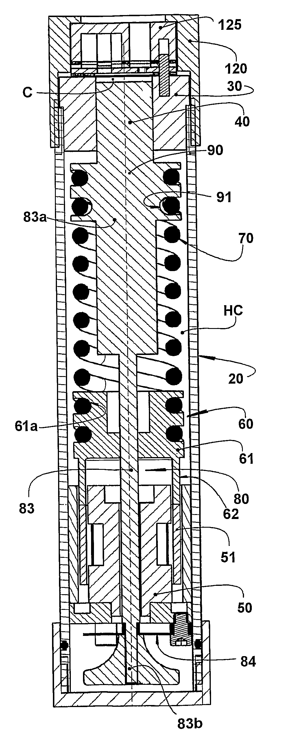
[0042]The present invention comprises a compressor for refrigeration systems, for example, as set forth in FIG. 3, a compact compressor of the type to be particularly, but not exclusively, utilized to refrigerate electronic systems, said compressor generically comprising a shell 20; a cylinder 30 affixed to the shell 20 and defining a compression chamber C; a piston 40 reciprocating in the interior of the compression chamber C during the operation of the compressor; a linear electric motor 50 mounted to the shell 20; an actuating means 60 operatively coupling the piston 40 to the linear electric motor 50, so as to make the latter displace the piston 40 in a reciprocating movement inside the compression chamber C.

[0043]In the solution of the present invention, the actuating means 60 is coupled to the piston 40 by an elastic means 70 designed so that the actuating means 60 and the piston 40 are displaced in phase opposition during the operation of the compressor, as exposed ahead.

[004...


PUM


Abstract

The invention refers to a linear compressor, comprising: a shell (20); a cylinder (30) affixed to the shell (20) and defining a compression chamber (C); a piston (40) to be displaced in reciprocating movement in the interior of the compression chamber (C) during the operation of the compressor; a linear electric motor (50) mounted to the shell (20); and an actuating means (60) operatively coupling the piston (40) to the linear electric motor (50), in order to make the latter displace the piston (40) in a reciprocating movement in the interior of the compression chamber (C), the actuating means (60) being coupled to the piston (40) by an elastic means (70), so that the actuating means (60) and the piston (40) be displaced in phase opposition during the operation of the compressor.

Description

CROSS-REFERENCE OF RELATED APPLICATIONS[0001]This application is a US National Phase Application under 35 U.S.C. §371 of International Patent Application No. PCT / BR2007 / 000098 filed Apr. 17, 2007, which claims priority to and the benefit of, Brazilian Patent Application No. PI0601645-6, filed Apr. 18, 2006, each of which are hereby incorporated by reference in their entirety.FIELD OF THE INVENTION[0002]The present invention refers to a construction for a linear compressor and, more particularly, to a mounting arrangement for a linear compressor of the type generally used in small refrigeration systems, which allows for the distribution of the forces transmitted from the compressor components to the shell, to which the compressor is mounted. The present compressor can be constructed to be used not only in the refrigeration systems of refrigeration appliances in general, but also for refrigerating the components of compact electronic appliances, or other applications that require the ...

Claims


Application Information

Patent Timeline
Patent Type & Authority Patents(United States)
IPC IPC(8): F04B17/04
CPCF04B35/045F04B39/127F04B2201/0201F04B35/04F04B39/12F04B17/04
Inventor LILLIE, DIETMAR ERICH BERNHARDBERWANGER, EGIDIOBOSCO, JR., RAULMOREIRA, EMERSONGOERGEN, DAVI LUISPOSSAMAI, FABRICIO CALDEIRA
Owner EMBRACO IND DE COMPRESSORES E SOLUCOES EM REFRIGERACAO LTDA
Learn More