Composite memory device, data processing method and data processing program

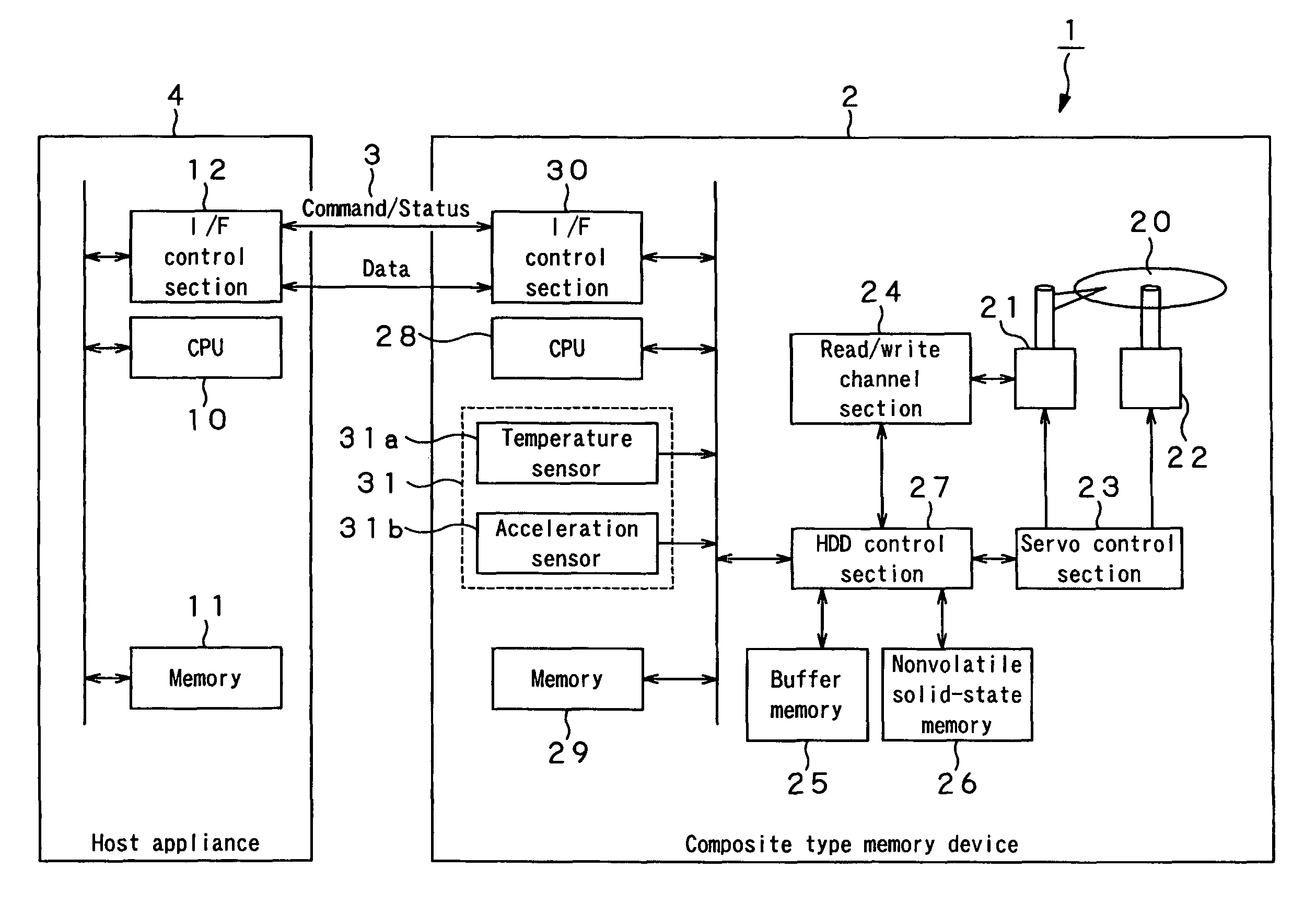
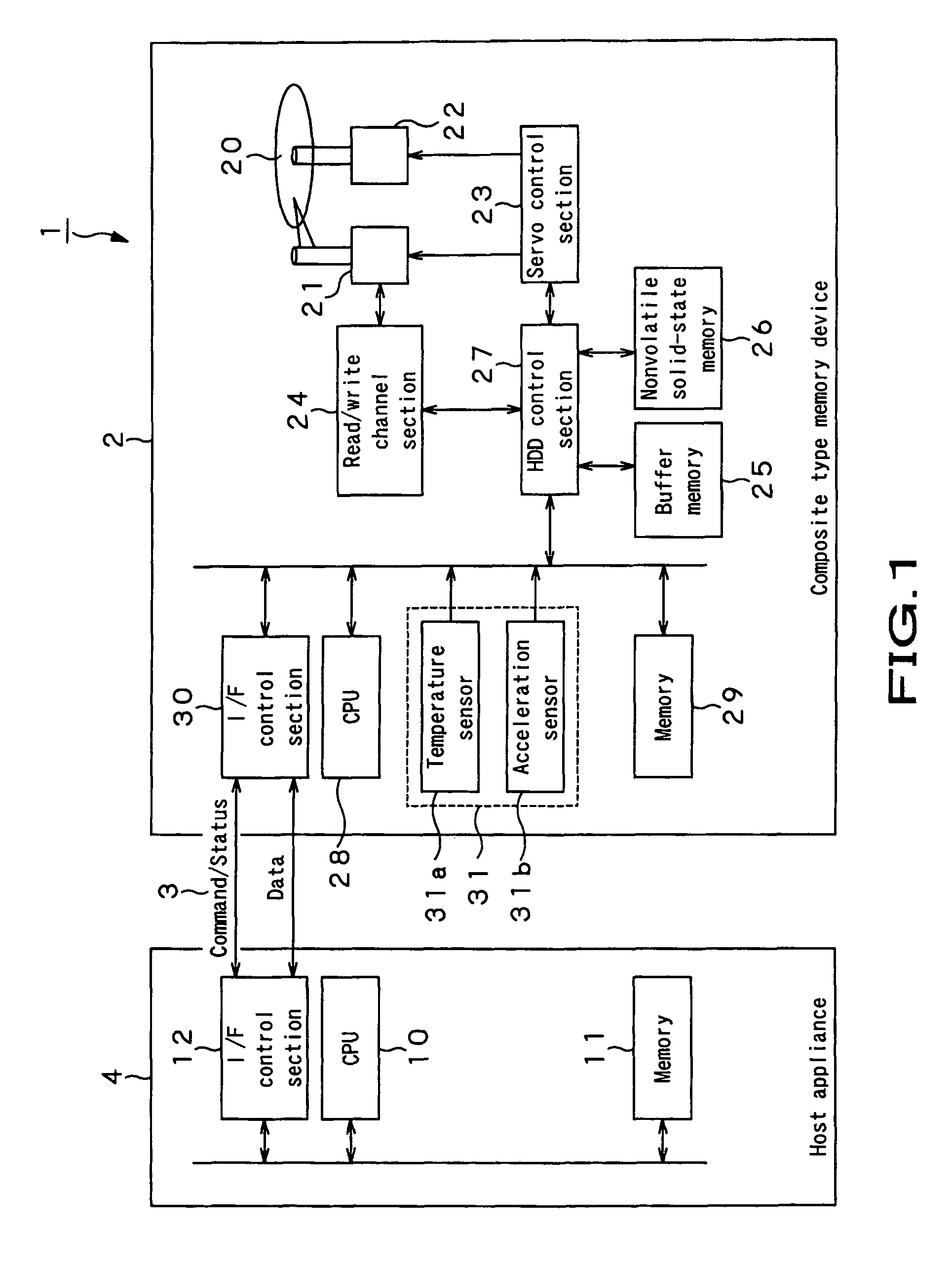
a memory device and data processing technology, applied in the field of composite memory devices, can solve problems such as vibration-prone hdds

Inactive Publication Date: 2012-08-14
SONY CORP
View PDF15 Cites 9 Cited by
  • Summary
  • Abstract
  • Description
  • Claims
  • Application Information

AI Technical Summary

Benefits of technology

[0018]Thus, a highly efficient memory device can be realized by combining a nonvolatile solid-state memory and a large capacity HDD. More specifically, it will be possible to realize a low cost high reliability storage device when the nonvolatile solid-state memory is utilized as data storage area for storing data to be accessed frequently and to be used in a transient state while the HDD is utilized as recording area to be used in a steady state.
[0027]Additionally, according to the invention, it is possible to automatically move the saved data temporarily written to the nonvolatile solid-state memory to the proper data region where the saved data are to be written without transferring the data between the composite memory device and a host appliance and reconstruct the file allocation table according to the configuration of the moved cluster.
[0028]Still additionally, according to the invention, it is possible to construct a highly reliable hybrid storage system that is equipped with a sensor for detecting impacts and vibrations and adapted to switch data from a nonvolatile solid-state memory to a recording medium or vice versa depending on the outcome of the detecting operation of the sensor so that a free region can be automatically secured in the nonvolatile solid-state memory by automatically writing back the saved data to the data region of the recording medium if the nonvolatile solid-state memory has only a small recording capacity.

Problems solved by technology

Additionally, the HDD is prone to be damaged by vibrations and impacts because it involves mechanical operations when accessing data.

Method used


Image

  • Composite memory device, data processing method and data processing program
  • Composite memory device, data processing method and data processing program
  • Composite memory device, data processing method and data processing program

Examples


example 1

The (Move) Process of Moving Data from the Data Area DA2 to Data Area DA1

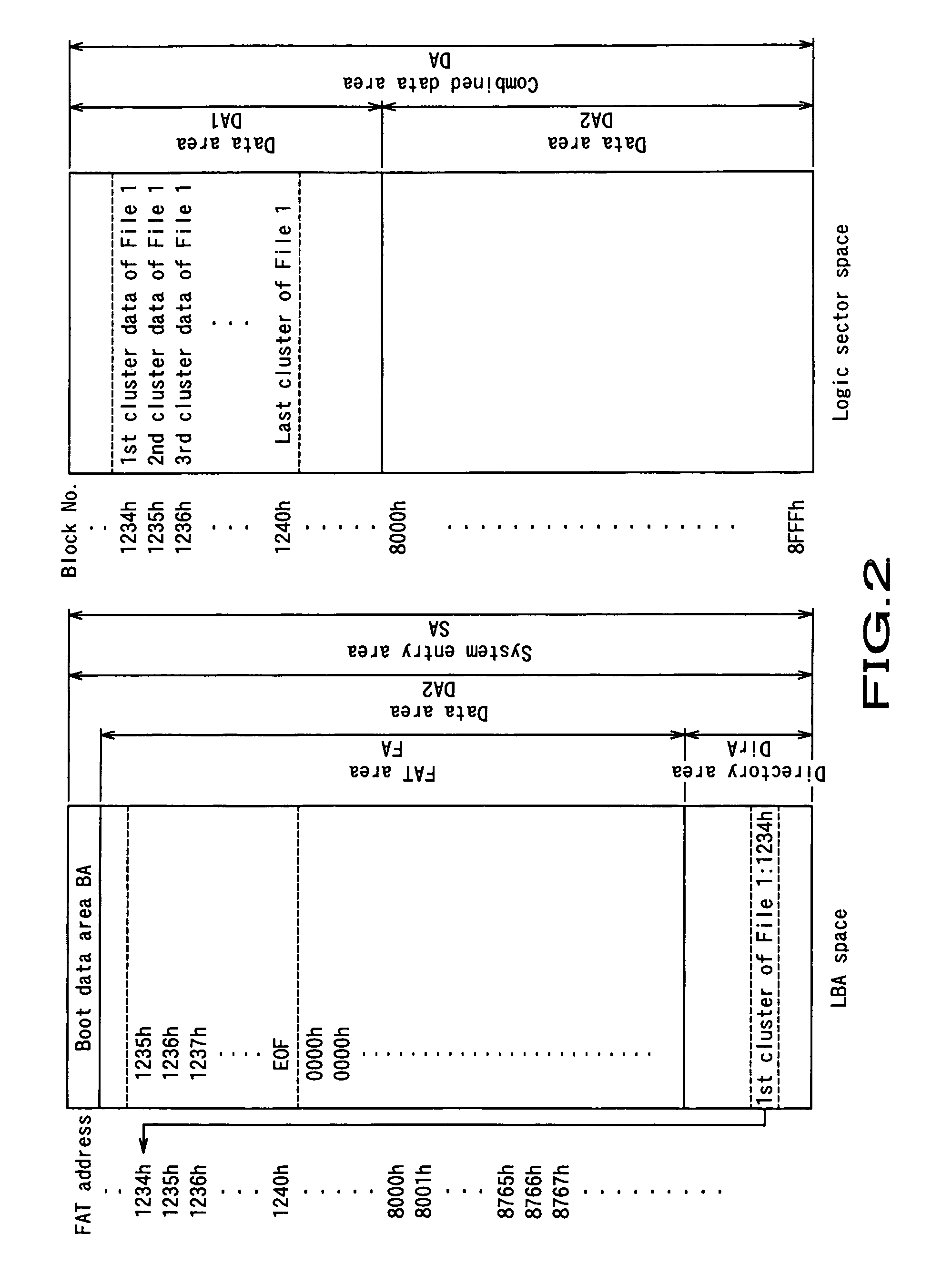
[0105]Now, the sequence of the process of moving the data file (File 1) recorded in the data area DA2 of the nonvolatile solid-state memory 26 of the composite memory device 2 to the data area DA1 of the recording medium 20 (move process) when File 1 is a file that is accessed scarcely will be described below by referring to the flowchart of FIG. 6. More specifically, it is assumed here that File 1 that is written to “20761h-20766h” of data area DA2 is moved to the free area “01231h-01236h” of the data area DA1 by using the LBA (logical block address) space and the logic sector space as shown in FIG. 7. Note that FIG. 7 illustrates the state of the file before the move process.

[0106]The host appliance 4 issues a command to the composite memory device 2, asking to notify it of the leading cluster address of File 1. In response to the command issued from the host appliance 4, the composite memory device 2 transmi...

example 2

The (Move) Process of Moving Data from the Data Area DA1 to Data Area DA2

[0121]Now, the sequence of the process of moving the data file (File 1) recorded in the data area DA 1 of the recording medium 20 of the composite memory device 2 to the data area DA2 of the nonvolatile solid-state memory 26 (move process) when File 1 is a file that is accessed frequently will be described below by referring to the flowchart of FIG. 12. More specifically, File 1 that is written to “01231h-01236h” of data area DA1 is moved to the free area “20761h-20766h” of the data area DA2 by using the LBA (logical block address) space and the logic sector space as shown in FIG. 13.

[0122]The host appliance 4 issues a command to the composite memory device 2, asking to notify it of the leading cluster address of File 1. In response to the command issued from the host appliance 4, the composite memory device 2 transmits the leading cluster address “01231h” of File 1 from the directory area DirA. Then, the host ...

example 3

The (Copy) Process of Copying Data from the Data Area DA2 to Data Area DA1

[0137]Now, the sequence of the process of copying the data file (File 1) recorded in the data area DA 2 of the nonvolatile solid-state memory 26 of the composite memory device 2 to the data area DA1 of the recording medium 20 (copy process) when File 1 is a file that is accessed scarcely will be described below by referring to the flowchart of FIG. 16. More specifically, File 1 that is written to “120761h-20766h” of data area DA2 is copied to the free area “01231h-01236h” of the data area DA1 by using the LBA (logical block address) space and the logic sector space.

[0138]The host appliance 4 issues a command to the composite memory device 2, asking to notify it of the leading cluster address of File 1. In response to the command issued from the host appliance 4, the composite memory device 2 transmits the leading cluster address “20761h” of File 1 from the directory area DirA. Then, the host appliance 4 issues...


PUM


Abstract

A composite memory device, a data processing method and a data processing program can efficiently and selectively use a nonvolatile solid-state memory and a recording medium. The composite medium device includes a nonvolatile solid-state memory and a recording medium and is adapted to combine the data area of the recording medium and the data area of the nonvolatile solid-state memory and manage them as totally or partly integrated data area by means of a predetermined file system. The composite memory device is connected to a host appliance by way of an interface section.

Description

CROSS REFERENCES TO RELATED APPLICATIONS[0001]The present invention contains subject matter related to Japanese Patent Applications JP 2005-064518 and 2005-215105 filed in the Japanese Patent Office respectively on Mar. 8, 2005 and on Jul. 25, 2005, the entire contents of which being incorporated herein by reference.BACKGROUND OF THE INVENTION[0002]This invention relates to a composite memory device including a recording medium and a nonvolatile storage medium so that data may be written to and read out from it on the basis of a file system that is common to them and also to a data writing method and a data writing program for writing data to such a composite memory device.[0003]Hard disc drives (to be referred to simply as HDDs hereinafter) are being popularly used as external storage devices for personal computers (PCs) and made to have larger memory capacities as a result of improvements on recording density. They have been finding and are being expected to find applications in t...

Claims


Application Information

Patent Timeline
Patent Type & Authority Patents(United States)
IPC IPC(8): G06F12/00
CPCG11B20/10G11B27/329G06F3/0625G06F3/065G06F3/068G06F11/1441G06F12/0866G11B2220/2516G11B2220/45G11B2220/61G11B2220/652G11B2220/657Y02B60/1246Y02D10/00G01F15/10G01F15/14
Inventor SUZUKI, KAZUYANISHIMURA, HAJIMETAMURA, TETSUYASASA, TAKESHI
Owner SONY CORP
Why Eureka
Try Eureka