Flush mounting apparatus and methods using component cover

a technology of component covers and mounting apparatus, which is applied in the direction of machine supports, building repairs, applications, etc., can solve the problems of affecting the appearance of flush mounts, allowing the component covers to be easily removed, and the wallboards generally cannot support the weight of heavy speakers over time, so as to prevent scratching and facilitate installation

Active Publication Date: 2012-08-21
DANA INNOVATIONS
View PDF6 Cites 14 Cited by
  • Summary
  • Abstract
  • Description
  • Claims
  • Application Information

AI Technical Summary

Benefits of technology

[0011]An electronic remote could unlock the locking mechanism, for example a radio frequency transmitter or a passive RFID tag, but the key to unlock the component cover is preferably a low tech solution. For example, a magnet could slide a bolt or latch to the side, or a screwdriver could unscrew a bolt running through the component and the receiver. A user could also simply overpower the locking mechanism by pulling the component from the receiver using a gripping surface, for example a handle, outcropping, or a loop. Where the front surface of the component cover is without a gripping surface, a vacuum or magnetic force could be used. Vacuum grippers could provide a powerful vacuum force by combining a lever with a suction cup, and electromagnets or lodestones could provide a powerful magnetic force.
[0015]When the component cover is placed within the “cover recess” formed in the panel, the cover covers at least a portion of the front of the component. Preferably the component cover covers the entire surface of the component so that it can not be seen from a front of the wallboard. The component cover does not need to directly touch the component and could have an object interposed between the component cover and the component. For example, a static-free sheet could be interposed between the two in order to prevent scratching.
[0016]Panels are typically installed into the wallboard by first approximating the edges of the panel with the edges of the wallboard. “Approximating” is defined herein to mean bringing the edges near or towards one another so that the junction or gap between the edges is less than 10 mm (0.394 in), more preferably less than 5 mm (0.197 in), or most preferably less than 2 mm (0.079 in). If the junction or gap between the edges is larger, a spacer can be attached to the edge of the panel before installation, or one or more shims can be installed into the junction. The junction can then be concealed using a suitable construction method, for example taping or plastering over the junction. Providing a pre-fabricated panel designed to accept specific components greatly facilitates installation by eliminating the need for on-site precision measurements.

Problems solved by technology

Shotey's component cover, however, requires the installer to install the outlet box along a support strut, such that the component cover extends outward from the front of the wallboard, preventing a flush-mounted appearance.
While Curtis allows a speaker to be clamped in any location along the surface of a wallboard, wallboards generally can't support the weight of heavy speakers over time.
Hagman, however, does not allow the component cover to be easily removed after spackling, and does not provide an easy way to remove the speaker if it needs to be maintained.

Method used


Image

  • Flush mounting apparatus and methods using component cover
  • Flush mounting apparatus and methods using component cover
  • Flush mounting apparatus and methods using component cover

Examples


Embodiment Construction

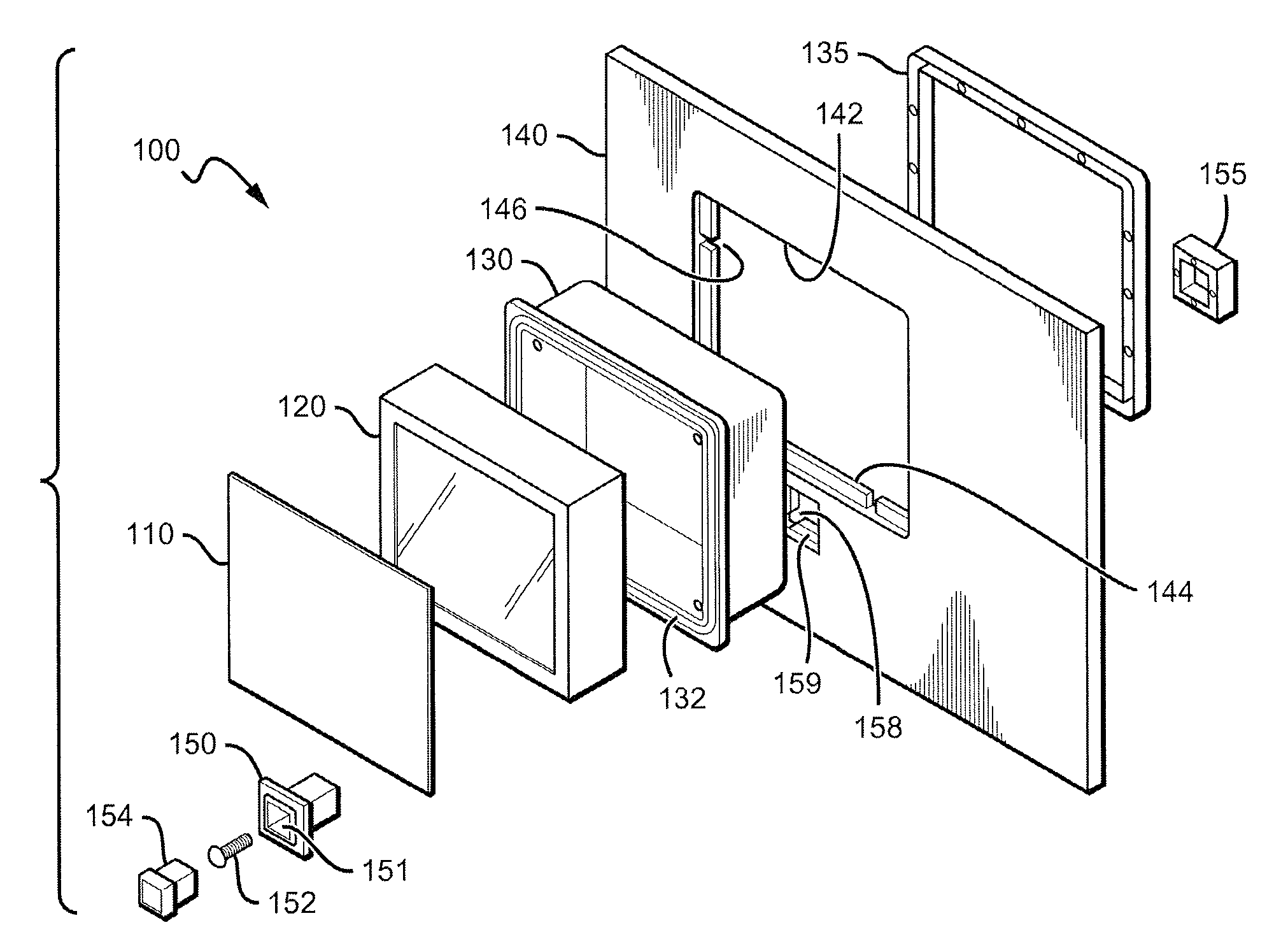
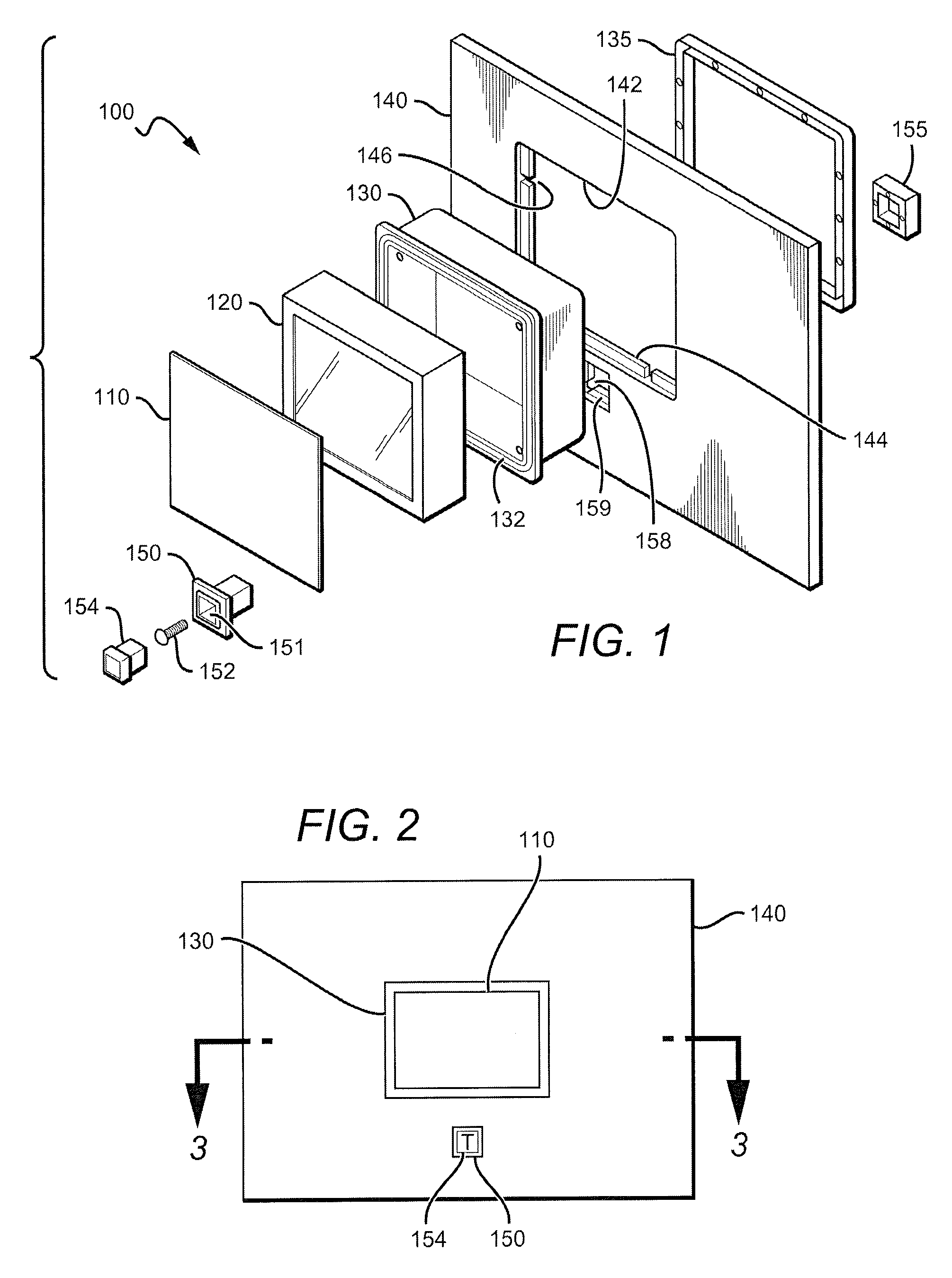
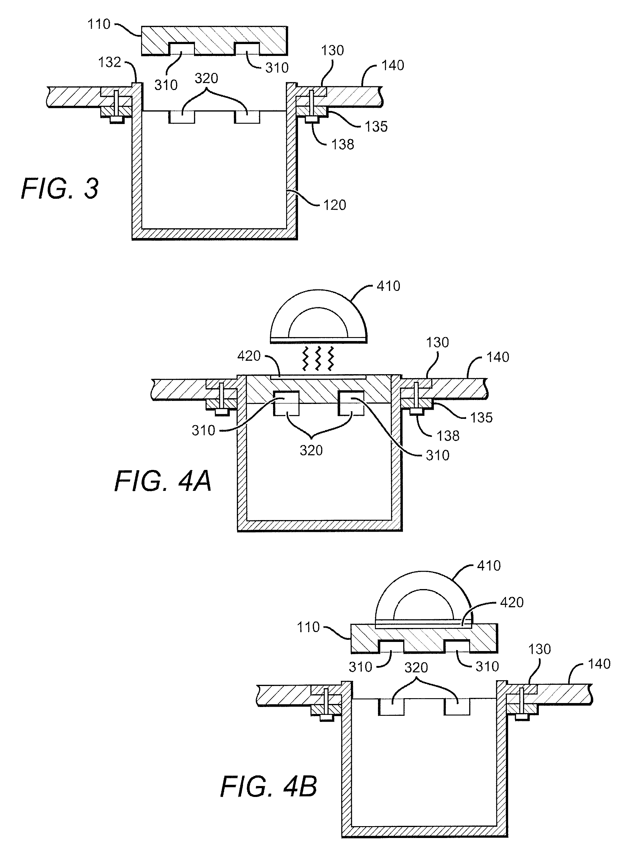
[0044]In FIG. 1, a panel 140 is used to mount a component 120 to a wallboard (not shown). Generally, panel 140 has an opening 142 and recessed projections 144. Front bracket 130 and back bracket 131 clamp onto recessed projections 144, and then component 120 could be placed within the completed bracket. Lastly, component cover 110 is placed over component 120 to cover at least a portion of the front of component 120.

[0045]Panel 140 is a piece of gypsum board, wood, plastic, or other material (or combination of materials) sufficiently strong to support a speaker or other desired component between two studs of a wall, or joists or other supports in a ceiling. Where plywood is used as the panel material, for example, the panel might be as thin as ¼″ (6.31 mm), but would more preferably measure at least ½″ (12.7 mm) or ⅜″ (19.01 mm). Preferred materials include wallboard, Medium Density Fiberboard (MDF), High Density Fiberboard (MDF), Acrylonitrile Butadiene Styrene (ABS), and other mat...


PUM


Abstract

A panel with a bracket is used to install a component to a wallboard. The panel is inserted into an opening to a wallboard, and the junction between the panel and the wallboard is taped and spackled so that the wallboard and panel appear to be a single object. When the component is fully coupled to the bracket, the front of the component is slightly recessed from the front of the panel. A component cover could then be inserted into the newly created recess so that the component appears to be completely flush with the wallboard.

Description

[0001]This application is a continuation-in-part of non-provisional application Ser. No. 12 / 202,870 filed Sep. 2, 2008. Ser. No. 12 / 202,870 is a continuation-in-part of non-provisional application Ser. No. 11 / 954,667 filed Dec. 12, 2007. Ser. No. 11 / 954,667 is a continuation-in-part of non-provisional application Ser. No. 11 / 566,365 filed Dec. 4, 2006, and Ser. No. 11 / 954,667 also claims priority to (1) provisional application Ser. No. 60 / 950,237 filed Jul. 17, 2007 and (2) International application Ser. No. PCT / US07 / 16404 filed Jul. 19, 2007. Ser. No. 11 / 566,365 claims priority to provisional application Ser. No. 60 / 825,162 filed Sep. 11, 2006. PCT / US07 / 16404 claims priority to (1) non-provisional application Ser. No. 11 / 548,381 filed Oct. 11, 2006, (2) provisional application 60 / 825,162 filed Sep. 11, 2006, and (3) provisional application 60 / 950,237 filed Jul. 17, 2007. All prior applications are incorporated by reference in their entirety.FIELD OF THE INVENTION[0002]The field of ...

Claims


Application Information

Patent Timeline
Patent Type & Authority Patents(United States)
IPC IPC(8): E04F19/00
CPCH02G3/00H02G3/123H02G3/14H04R1/025H04R2201/021H04R2499/13
Inventor STRUTHERS, SCOTTCALL, RAY
Owner DANA INNOVATIONS
Why Eureka
Try Eureka