Ratchet wrench

a ratchet wrench and ratchet technology, applied in the field of ratchet wrenches, can solve the problems of one-way ratchet mechanism that cannot be easily controlled or changed to the reverse drive direction, and achieve the effects of convenient operation or actuation, improved and simplified, and easy and quick manufacturing and assembly

Inactive Publication Date: 2012-08-21
CHAN MENG TSUNG
View PDF10 Cites 15 Cited by
  • Summary
  • Abstract
  • Description
  • Claims
  • Application Information

AI Technical Summary

Benefits of technology

[0020]The primary objective of the present invention is to provide a ratchet wrench including an improved and simplified structure for being easily and quickly manufactured and assembled and for being easily operated or actuated by the user without an actuating knob or switching device.

Problems solved by technology

However, the typical reversible ratchet wrench includes a one-way ratchet mechanism that may not be easily controlled or changed to the reverse drive direction.

Method used


Image

  • Ratchet wrench
  • Ratchet wrench
  • Ratchet wrench

Examples


Embodiment Construction

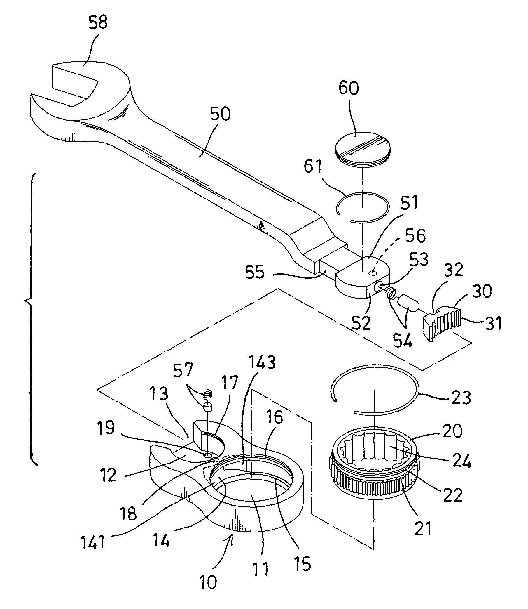
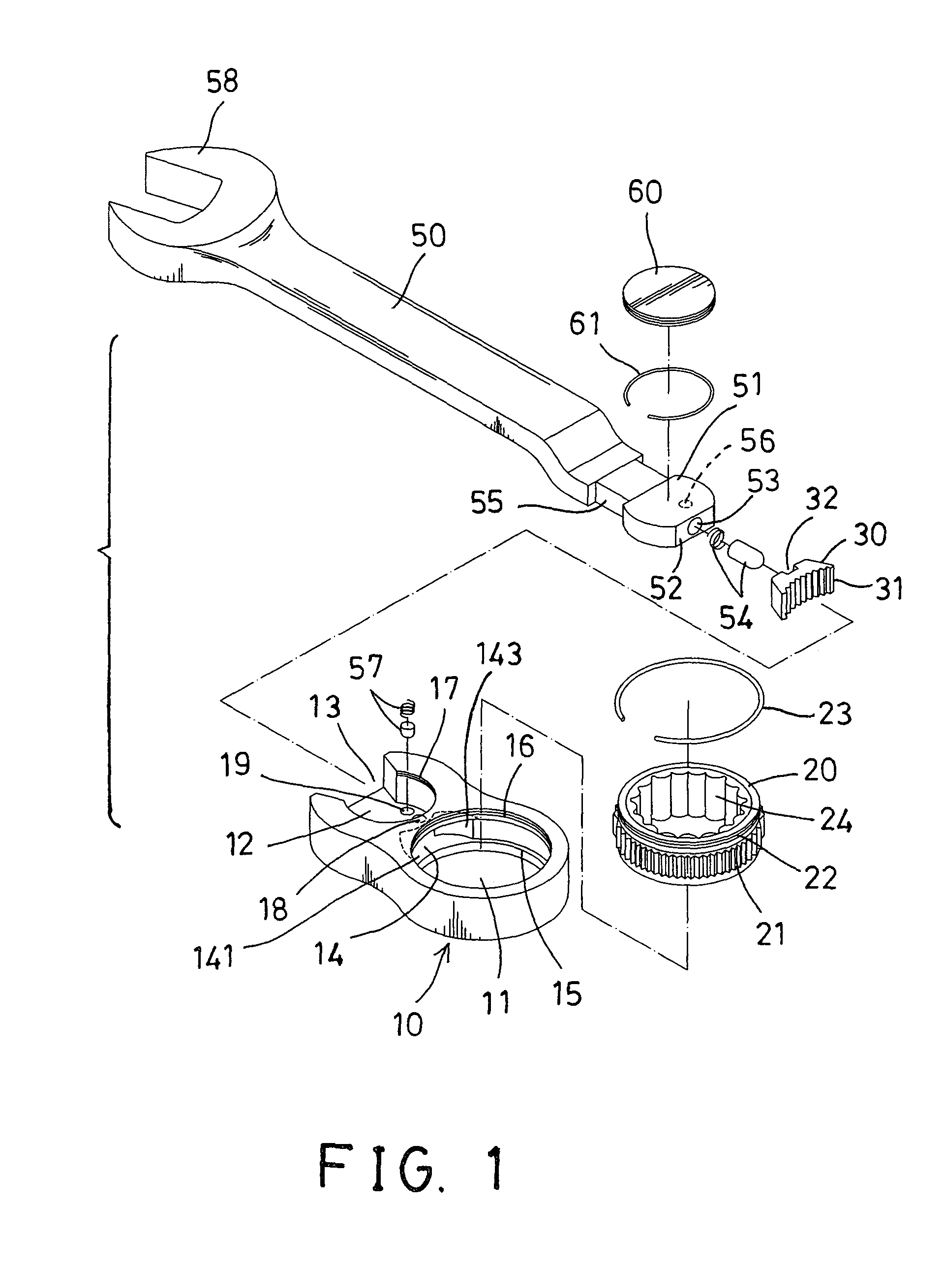
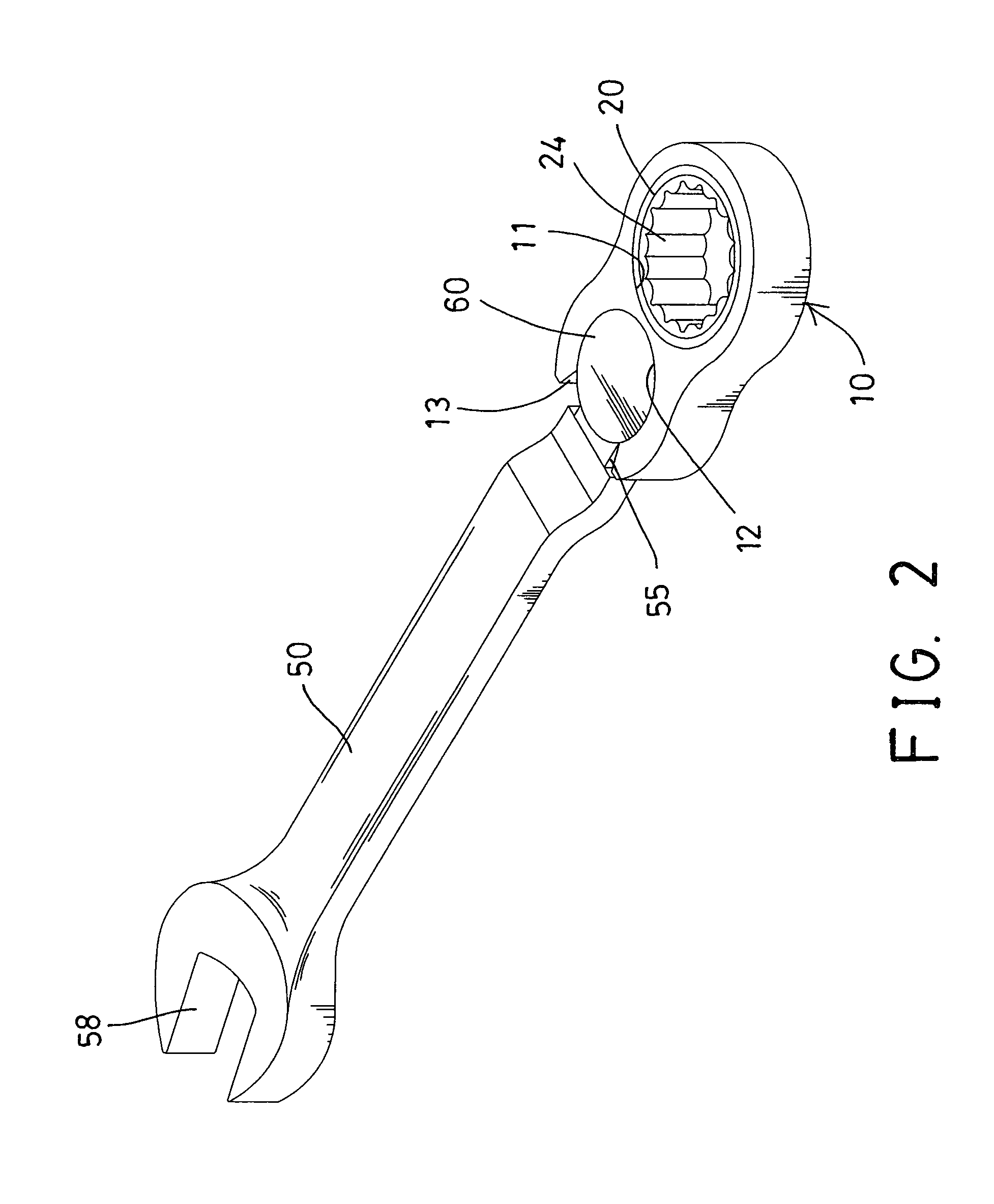
[0030]Referring to the drawings, and initially to FIGS. 1-3, a ratchet wrench in accordance with the present invention comprises a box end or wrench head 10 including a chamber 11, such as a circular or cylindrical chamber 11 formed therein, and including a notch 12 formed therein and spaced or disengaged from the chamber 11 of the wrench head 10 and having a sector-shaped opening 13 communicative with the notch 12 of the wrench head 10, and including a passage or pawl compartment 14 formed therein and located between the notch 12 and the chamber 11 of the wrench head 10 and communicative with the notch 12 and the chamber 11 of the wrench head 10, in which the notch 12 of the wrench head 10 includes a radian or arc having more than 180 degrees or more than one half of a circle.

[0031]The wrench head 10 includes a peripheral shoulder 15 formed in the upper or lower portion of the wrench head 10 and communicative with the chamber 11 of the wrench head 10, and includes a peripheral groo...


PUM


Abstract

A ratchet wrench includes a wrench head having a pawl compartment formed between a notch and a chamber of the wrench head, a drive member mounted in the chamber of the wrench head and having a ratchet gear, a pawl slidably received in the pawl compartment of the wrench head for engaging with the ratchet gear and for controlling the driving direction of the drive member by the wrench head, a handle having a pivotal coupling member mounted in the notch of the wrench head, and an actuating member attached to the pivotal coupling member and engaged with the pawl for moving the pawl to either side of the pawl compartment of the wrench head in order to determine the driving direction of the drive member by the wrench head.

Description

BACKGROUND OF THE INVENTION[0001]1. Field of the Invention[0002]The present invention relates to a ratchet wrench, and more particularly to a ratchet wrench including an improved and simplified structure for being easily and quickly manufactured and assembled and for being easily operated or actuated by the user without an actuating knob or switch.[0003]2. Description of the Prior Art[0004]Typical ratchet wrenches comprise a head with an aperture there-through having ratchet teeth thereon, a drive member mounted for rotation relative to the head and defines a slide surface facing the ratchet teeth on the head, a pawl positioned between the slide surface and the head with the pawl having two sets of ratchet teeth for determining the driving direction of the drive member by the head.[0005]For example, U.S. Pat. No. 4,520,697 to Moetteli discloses one of the typical ratchet wrenches also comprising a drive member mounted in the aperture of the head for rotation relative to the head, a ...

Claims


Application Information

Patent Timeline
Patent Type & Authority Patents(United States)
IPC IPC(8): B25B13/46
CPCB25B13/463
Inventor CHAN, MENG TSUNG
Owner CHAN MENG TSUNG
Why Eureka
Try Eureka