Thrombus removal device

a technology of thrombosis and thrombosis, which is applied in the field of medical devices, can solve the problems of corkscrew devices, which may be even more difficult to remove, and all of these devices, and achieve the effect of small and flexibl

Active Publication Date: 2012-08-21
COOK MEDICAL TECH LLC
View PDF24 Cites 144 Cited by
  • Summary
  • Abstract
  • Description
  • Claims
  • Application Information

AI Technical Summary

Benefits of technology

[0010]The present invention provides a thrombus removal device that is small and flexible to, for example, capture clots in the cerebral vasculature. The distal tip of the device is configured as a loop to eliminate the danger of inadvertently penetrating through an artery wall while attempting to capture the clot.

Problems solved by technology

All of these devices may, however, have certain disadvantages.
The process of penetrating the clot with the balloon catheter device tends to push the clot deeper into the arterial circulation where it becomes even more difficult to remove.
This issue also occurs with basket and corkscrew devices that are collapsed into an outer delivery sheath and passed through the clot before they can be deployed and retracted.
The action of pushing a device through the center of the clot pushes the clot deeper into the artery and sometimes fragments the clot, making it into an even more dangerous embolus.
These counter forces tend to macerate or fragment the clot and result in only a small part of the clot being captured.
Such devices are seldom used since they carry the very high risk of penetrating the vessel wall.
Another issue associated with conventional thrombectomy devices is that they are typically too large and too stiff for use in the small tortuous vessels of the brain.
These support structures will also displace clots, making it difficult to capture all the clot material.
Still another issue includes capturing any of the loose fragments possibly dislodged from the clot during removal of the clot.
Another issue arises if a thrombectomy device has a diameter smaller than the vessel diameter when deployed from the catheter.

Method used


Image

  • Thrombus removal device
  • Thrombus removal device
  • Thrombus removal device

Examples


Embodiment Construction

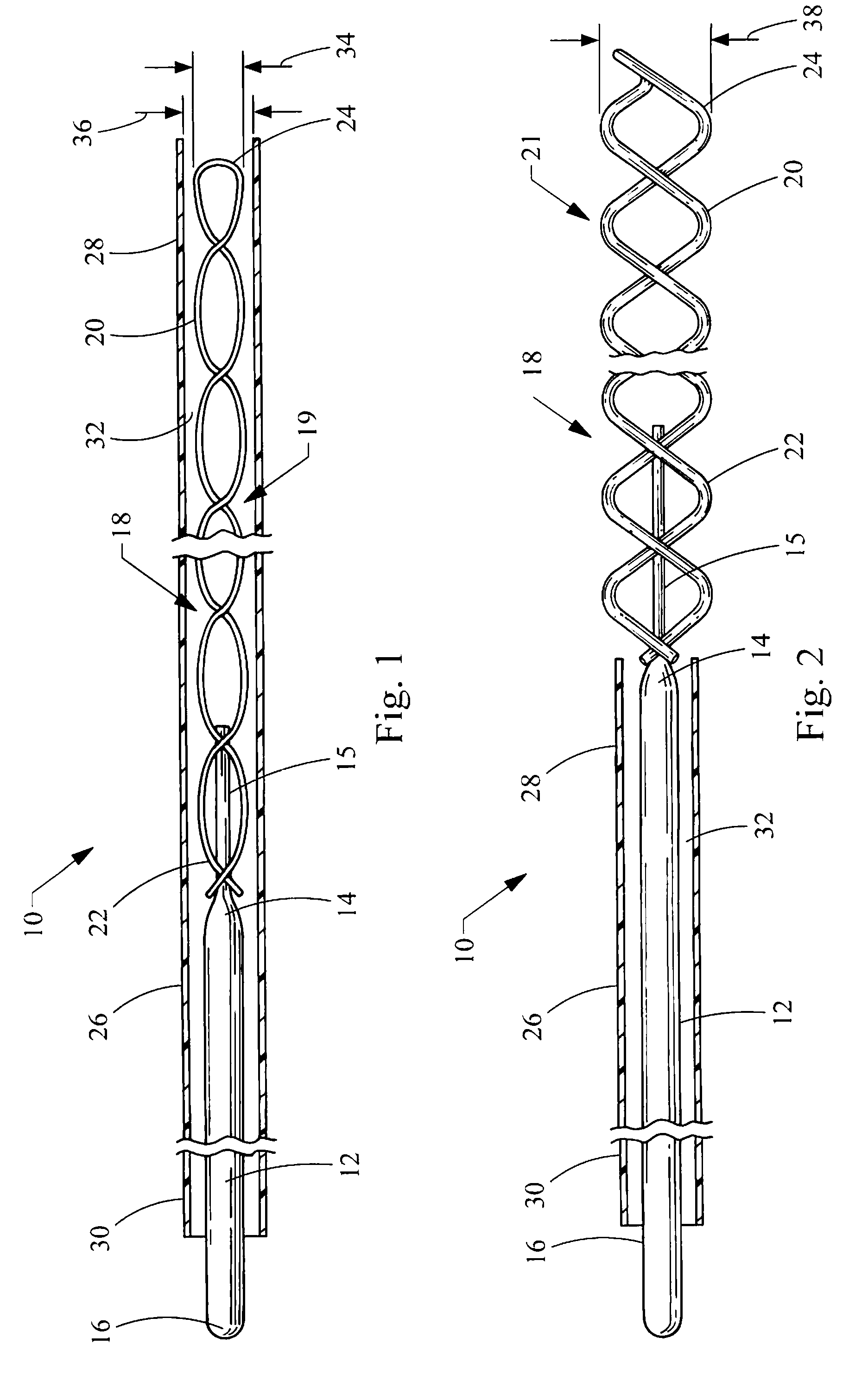
[0035]Referring now to FIG. 1, a thrombus removal device embodying the principles of the present invention is illustrated therein and designated at 10. As its primary components the device 10 includes a shaft 12 having a proximal end 16 extending to a distal end 14 attached to a helical coil 18. The helical coil 18 has a distal portion 20 including a distal tip 24 and a proximal portion 22. A sheath 26 having a distal end 28 and a proximal end 30 defines a lumen 32 within which the shaft 12 and helical coil 18 are disposed. The device 10 is small and flexible to enable the helical coil 18 to penetrate a thrombus or clot without posing a danger of penetrating a body vessel wall (not shown).

[0036]The helical coil 18 is made of wire and in FIG. 1 is shown in a closed configuration 19, compressed inside the lumen 32 of the distal end 28 of the sheath 26. In the closed configuration 19, the helical coil 18 has a first outer diameter 34. When the sheath 26 is retracted proximally in FIG. ...


PUM


Abstract

A thrombus removal device includes a shaft with a distal end and a proximal end, a sheath with a distal end and a proximal end, and a helical coil attached at a proximal end to the distal end of the shaft and is disposed within the lumen of the sheath in a closed configuration. The helical coil includes a plurality of body portions with turns spaced apart longitudinally and laterally to facilitate screwing the helical coil into a thrombus and also providing an open area into which the thrombus can be captured. A distal tip of the helical coil is provided with a loop, an angle of which is about the same as the angle of at least one body portion. The helical coil assumes an open configuration when the sheath is retracted proximally from the distal tip. An aspiration device may be provided in fluid communication with the center of the helical coil.

Description

CROSS-REFERENCE TO RELATED APPLICATIONS[0001]This application claims the benefit of U.S. Provisional Application Ser. No. 60 / 857,760, filed on Nov. 8, 2006, entitled “THROMBUS REMOVAL DEVICE,” the entire contents of which are incorporated herein by reference.BACKGROUND[0002]1. Field of the Invention[0003]The present invention relates to medical devices. Specifically, the invention relates to a device for removing blood clots or thrombi from body vessels, such as the small arteries associated with the brain.[0004]2. Description of Related Art[0005]Mechanical thrombectomy is a procedure that has been in widespread use for many years. Typical thrombectomy devices are balloons that are inflated in a vessel and then withdrawn to pull clots into a sheath which can be withdrawn from the patient to remove the clots. Other devices are simple open ended catheters into which a clot is aspirated and removed from the patient. Another thrombectomy device employs a basket device that is opened wit...

Claims


Application Information

Patent Timeline
Patent Type & Authority Patents(United States)
IPC IPC(8): A61B17/22A61D1/02
CPCA61B17/221A61B2017/00685A61B2017/00867A61B2017/2212A61B2217/005A61M1/0023A61M1/80
Inventor OSBORNE, THOMAS A.KUPPURATHANAM, SHYAM
Owner COOK MEDICAL TECH LLC
Why Eureka
Try Eureka