Hemodialysis systems and methods
What is Al technical title?
Al technical title is built by PatSnap Al team. It summarizes the technical point description of the patent document.
a technology of hemodialysis and dialysis equipment, applied in the direction of instruments, multi-stage water/sewage treatment, separation processes, etc., can solve the problems of large amount of dialysate needed for hemodialysis, inefficient hemodialysis, difficult and expensive,
Active Publication Date: 2012-08-21
DEKA PROD LLP
View PDF415 Cites 214 Cited by
Summary
Abstract
Description
Claims
Application Information
AI Technical Summary
This helps you quickly interpret patents by identifying the three key elements:
Problems solved by technology
Method used
Benefits of technology
Problems solved by technology
Many factors make hemodialysis inefficient, difficult, and expensive.
These factors include the complexity of hemodialysis, the safety concerns related to hemodialysis, and the very large amount of dialysate needed for hemodialysis.
Therefore any increase in the ease and efficiency of the dialysis process could have an impact on treatment cost or patient outcome.
Method used
Image
Click on the blue label to locate the original text in one second.
Reading with bidirectional positioning of images and text.
Examples
Embodiment Construction
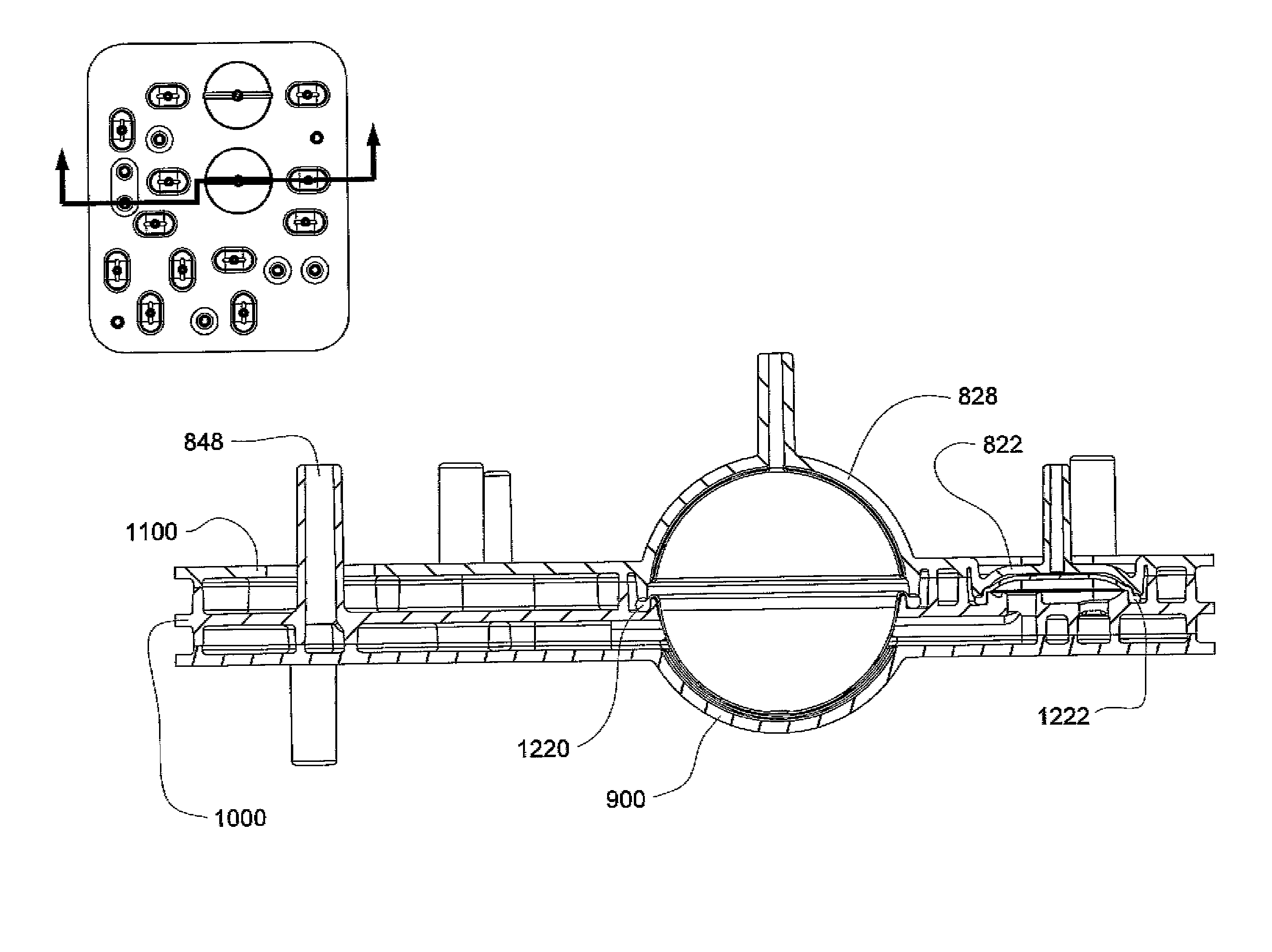
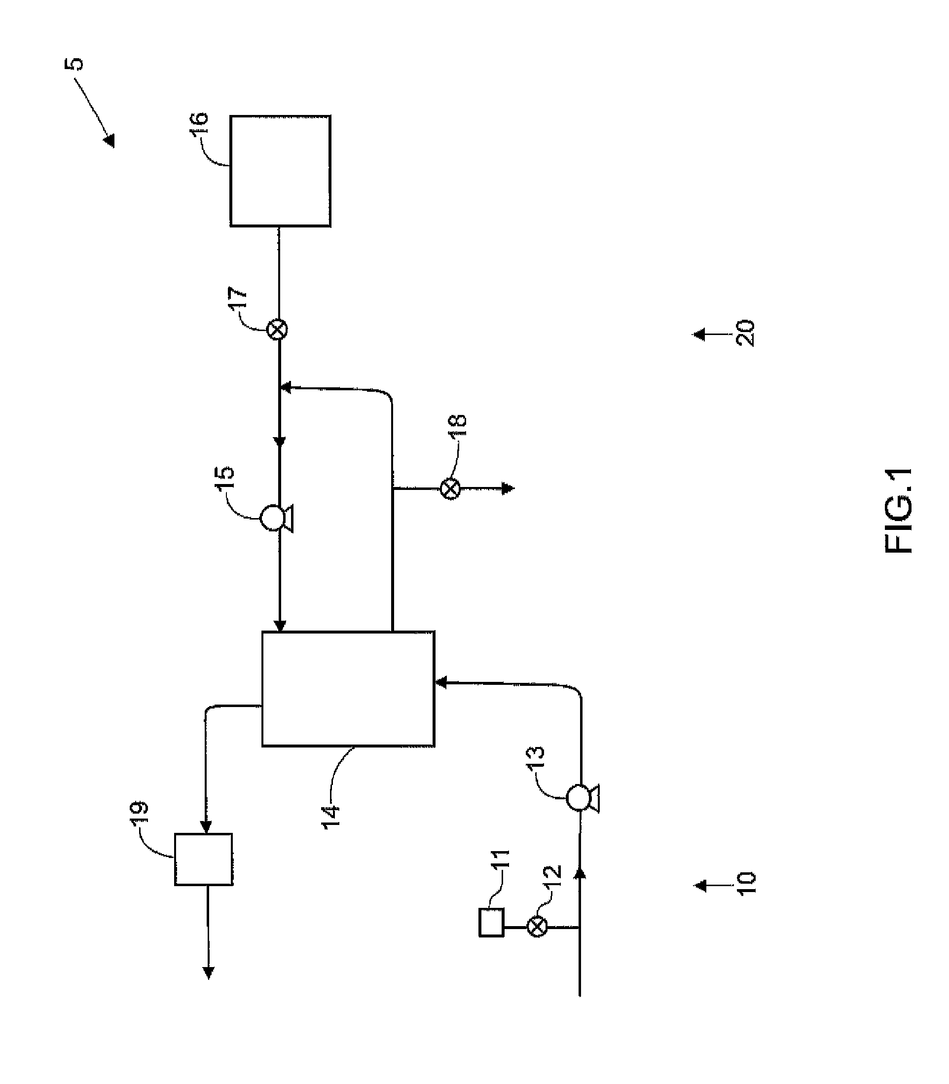
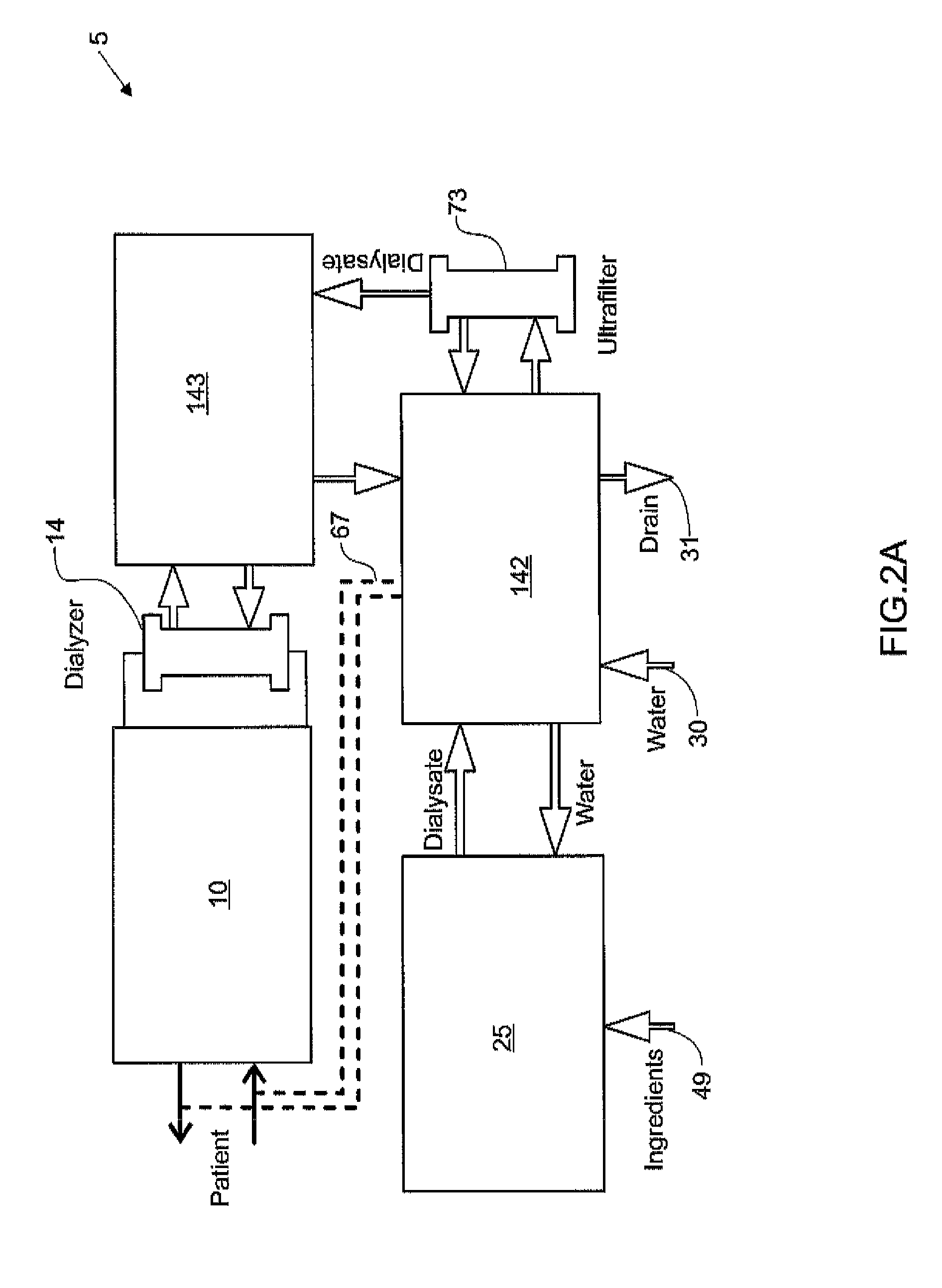
[0156]The present invention generally relates to hemodialysis and similar dialysis systems, including a variety of systems and methods that would make hemodialysis more efficient, easier, and / or more affordable. One aspect of the invention is generally directed to new fluid circuits for fluid flow. In one set of embodiments, a hemodialysis system may include a blood flow path and a dialysate flow path, where the dialysate flow path includes one or more of a balancing circuit, a mixing circuit, and / or a directing circuit. Preparation of dialysate by the mixing circuit, in some instances, may be decoupled from patient dialysis. In some cases, the circuits are defined, at least partially, within one or more cassettes, optionally interconnected with conduits, pumps, or the like. In one embodiment, the fluid circuits and / or the various fluid flow paths may be at least partially isolated, spatially and / or thermally, from electrical components of the hemodialysis system. In some cases, a g...
PUM
Property
Measurement
Unit
temperature
aaaaa
aaaaa
temperature
aaaaa
aaaaa
size
aaaaa
aaaaa
Abstract
The present invention generally relates to hemodialysis and similar dialysis systems, including a variety of systems and methods that would make hemodialysis more efficient, easier, and / or more affordable. One aspect of the invention is generally directed to new fluid circuits for fluid flow. In one set of embodiments, a hemodialysis system may include a blood flow path and a dialysate flow path, where the dialysate flow path includes one or more of a balancing circuit, a mixing circuit, and / or a directing circuit. Preparation of dialysate by the preparation circuit, in some instances, may be decoupled from patient dialysis. In some cases, the circuits are defined, at least partially, within one or more cassettes, optionally interconnected with conduits, pumps, or the like. In one embodiment, the fluid circuit and / or the various fluid flow paths may be at least partially isolated, spatially and / or thermally, from electrical components of the hemodialysis system. In some cases, a gas supply may be provided in fluid communication with the dialysate flow path and / or the dialyzer that, when activated, is able to urge dialysate to pass through the dialyzer and urge blood in the blood flow path back to the patient. Such a system may be useful, for example, in certain emergency situations (e.g., a power failure) where it is desirable to return as much blood to the patient as possible. The hemodialysis system may also include, in another aspect of the invention, one or more fluid handling devices, such as pumps, valves, mixers, or the like, which can be actuated using a control fluid, such as air. In some cases, the control fluid may be delivered to the fluid handling devices using an external pump or other device, which may be detachable in certain instances. In one embodiment, one or more of the fluid handling devices may be generally rigid (e.g., having a spheroid shape), optionally with a diaphragm contained within the device, dividing it into first and second compartments.
Description
RELATED APPLICATIONS[0001]This application claims the benefit of U.S. Provisional Patent Application Ser. No. 60 / 903,582, filed Feb. 27, 2007, entitled “Hemodialysis System and Methods,” and U.S. Provisional Patent Application Ser. No. 60 / 904,024, filed Feb. 27, 2007, entitled “Hemodialysis System and Methods.” Each of these is incorporated herein by reference.FIELD OF INVENTION[0002]The present invention generally relates to hemodialysis and similar dialysis systems, e.g., systems able to treat blood or other bodily fluids extracorporeally. In certain aspects, the systems includes a variety of systems and methods that would make hemodialysis more efficient, easier, and / or more affordable.BACKGROUND[0003]Many factors make hemodialysis inefficient, difficult, and expensive. These factors include the complexity of hemodialysis, the safety concerns related to hemodialysis, and the very large amount of dialysate needed for hemodialysis. Moreover, hemodialysis is typically performed in a...
Claims
Application Information
Patent Timeline
Application Date:The date an application was filed.
Publication Date:The date a patent or application was officially published.
First Publication Date:The earliest publication date of a patent with the same application number.
Issue Date:Publication date of the patent grant document.
PCT Entry Date:The Entry date of PCT National Phase.
Estimated Expiry Date:The statutory expiry date of a patent right according to the Patent Law, and it is the longest term of protection that the patent right can achieve without the termination of the patent right due to other reasons(Term extension factor has been taken into account ).
Invalid Date:Actual expiry date is based on effective date or publication date of legal transaction data of invalid patent.