Adjustable applicator

a technology of applicators and applicators, which is applied in the field of adjustable applicators, can solve the problems of inability to control the user's ability to achieve flexibility, difficult to apply, and difficult to learn to use rigid curved brushes in the confines of the eye area, so as to achieve constant rigidity and control of angular deformation

Active Publication Date: 2012-08-28
ZEN DESIGN SOLUTIONS
View PDF19 Cites 18 Cited by
  • Summary
  • Abstract
  • Description
  • Claims
  • Application Information

AI Technical Summary

Benefits of technology

[0022]According to an embodiment of the invention, the filament is so arranged as to cause progressive modification in the shape of the applicator element. The filament facilitates adjustment of the angular deformation of the applicator element.
[0044]According to an embodiment of the invention, there is provided an adjustable applicator wherein the user has more control over the angular deformation achieved in the applicator. Further, a constant rigidity of the applicator is provided as no additional component is inserted or withdrawn to achieve the straight or angularly deformed shape.

Problems solved by technology

However, the flexibility achieved is not controllable by the user.
Also, mascara, an important make-up accessory used to darken and define eyelashes to accentuate the eyes, is difficult to apply because of the target area of application.
However, the rigid curved brush is a more difficult instrument to learn to use in the confines of the eye area, particularly the corners of the eye where a straight brush works better.
Another drawback of pre-curved brush is that it is not readily adjustable to conform to a particular user's eyelid curvature.
In addition, the curvature of the upper and lower eyelids is rarely the same and a brush curved to fit the upper lid will not properly fit the lower lid.
Moreover, none of the designs propose a mechanism by which the applicator element could be straightened or curved to varying degrees without the usage of additional component.
Further, the deformation may be regular or irregular.

Method used


Image

  • Adjustable applicator
  • Adjustable applicator
  • Adjustable applicator

Examples


Embodiment Construction

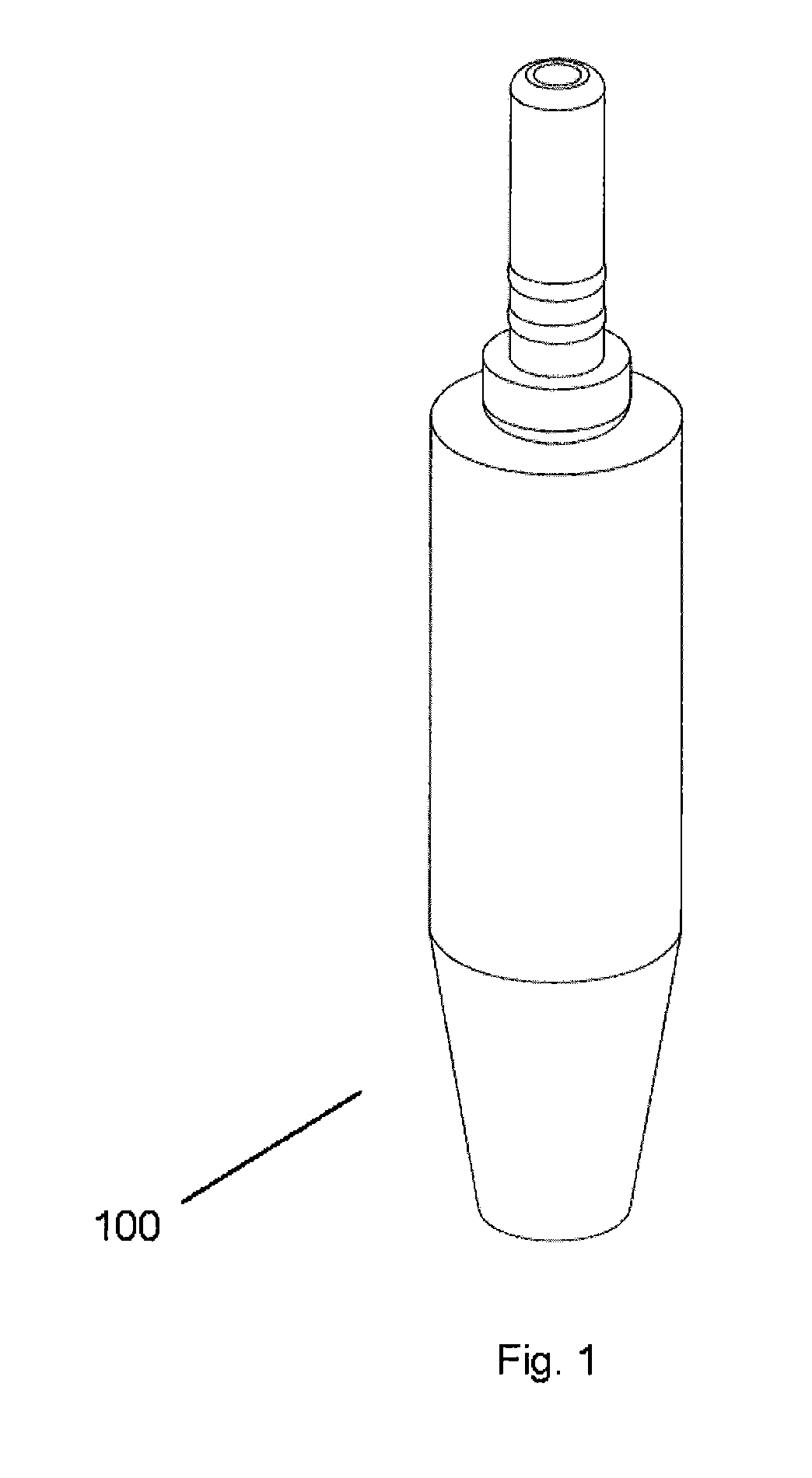
[0079]The adjustable applicator according to one embodiment of the present invention is shown in FIGS. 1 to 3.

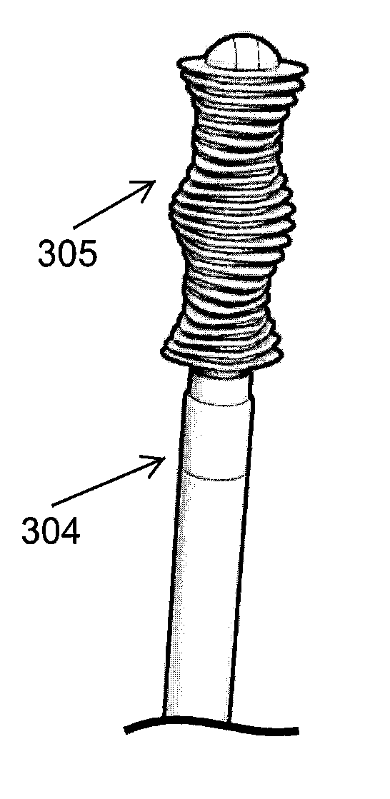
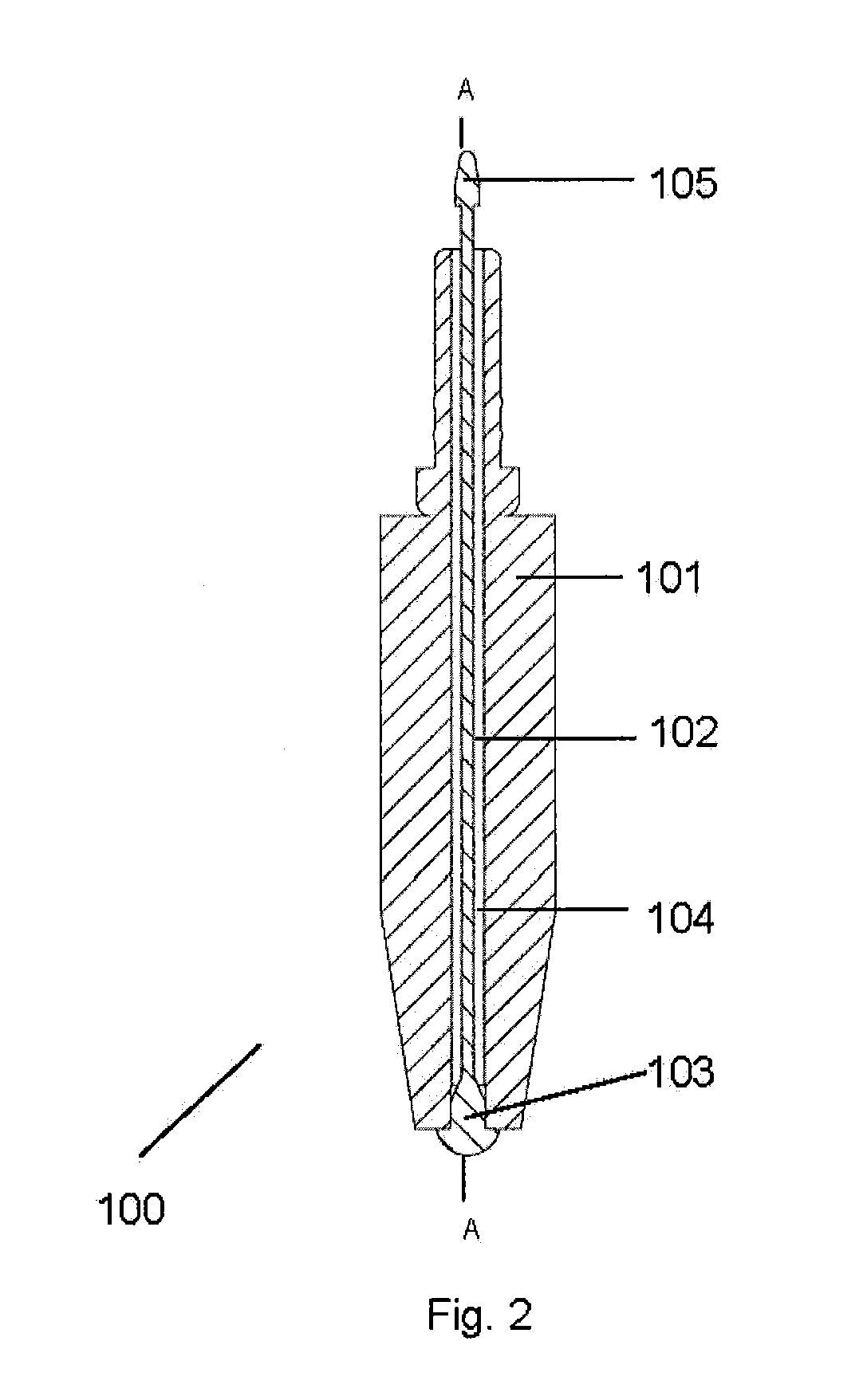
[0080]FIG. 1 is one embodiment of the present invention showing the adjustable applicator 100. The adjustable applicator 100 of the invention comprises of an applicator element 101 and a filament 102. In the applicator element 101 is a bore 104 housing the filament 102. The bore 104 may either be centrally or non-centrally aligned. The filament 102 is arranged to be movable inside the bore 104 of the applicator element 101. The applicator element 101 may be produced from an elastomer or any other elastic material allowing compression and expansion of the applicator. Further, the filament 102 may be made out of a material selected from a polymeric material and metals. The filament 102 is so arranged as to cause progressive angular deformation of the applicator element 101.

[0081]As shown in FIGS. 2 and 3, one end of the filament 102 is connected at a distal end 103 of the appl...


PUM


Abstract

An adjustable applicator employed for application of a cosmetic or a care product such as for application of mascara, coloring strands of hair, for dental flossing or for applying pharmaceuticals or cleaning agents is provided. In one embodiment, an adjustable applicator includes an applicator element having a bore, a filament wherein the filament is housed inside the bore of the applicator element and a clasping means wherein the applicator element angularly deforms when a force is applied on the clasping means such that the angular deformation occurs on the radial axis of the applicator element. Also disclosed is a device for packaging and dispensing a substance that includes an adjustable applicator.

Description

CROSS-REFERENCE TO RELATED APPLICATION[0001]This application is a continuation-in-part of U.S. patent application Ser. No. 12 / 363,117 filed Jan. 30, 2009, which is a continuation-in-part of U.S. patent application Ser. No. 12 / 025,249 filed Feb. 4, 2008 now abandoned, which are both incorporated by reference in its entirety.BACKGROUND[0002]1. Field of the Invention[0003]Embodiments of the present invention generally relate to adjustable applicators. More particularly the invention relates to applicators that can be adjusted as per user's convenience for application of a cosmetic or a care product.[0004]Applicators of the present invention can be employed in application of various products, such as for viscous cosmetics, for coloring strands of hair, and for dental flossing or for applying pharmaceuticals or cleaning agents.[0005]2. Description of the Related Art[0006]Various applicators for applying a substance are known. There are certain application areas where there is a requireme...

Claims


Application Information

Patent Timeline
Patent Type & Authority Patents(United States)
IPC IPC(8): A45D40/26A45D33/00
CPCA45D40/265A45D40/267A61C5/06A61C15/00A46B9/005A45D19/02A45D2200/1063A46B2200/1053A61C5/60
Inventor PIRES, LEO CLIFFORDHWANG, ROGERBOSE, RAHULBASAK, ABHISEKASTHANA, SHOURYAKOHLI, KOUSHIKMOHAPATRA, SANTOSH
Owner ZEN DESIGN SOLUTIONS
Why Eureka
Try Eureka