Male optical connector and female optical connector and related optical fiber coupling assembly

a technology of optical fiber coupling and female optical connector, which is applied in the field of optical technology, can solve the problems of destroying signal integrity, easy contamination of lenses, and reducing transmission efficiency

Inactive Publication Date: 2012-08-28
HON HAI PRECISION IND CO LTD
View PDF22 Cites 10 Cited by
  • Summary
  • Abstract
  • Description
  • Claims
  • Application Information

AI Technical Summary

Benefits of technology

[0004]Currently, an optical fiber coupling assembly is preferred for use in data transmission between electronic devices due to their high transmission speed and signal integrity. Generally, the optical fiber coupling assembly includes two optical fiber connectors, such as a male optical connector and a female optical connector, for coupling the optical fibers together to allow optical transmittance between the optical fibers. The connectors include lenses each being aligned with a corresponding optical fiber. When coupling connectors together, a lens in the male optical connector is aligned with a corresponding lens in the female optical connector to ensure the optical transmittance. However, when the connector is detached from the other connector, the lenses are easily contaminated. This decreases transmission efficiency and destroys the signal integrity.

Problems solved by technology

However, when the connector is detached from the other connector, the lenses are easily contaminated.
This decreases transmission efficiency and destroys the signal integrity.

Method used


Image

  • Male optical connector and female optical connector and related optical fiber coupling assembly
  • Male optical connector and female optical connector and related optical fiber coupling assembly
  • Male optical connector and female optical connector and related optical fiber coupling assembly

Examples


Embodiment Construction

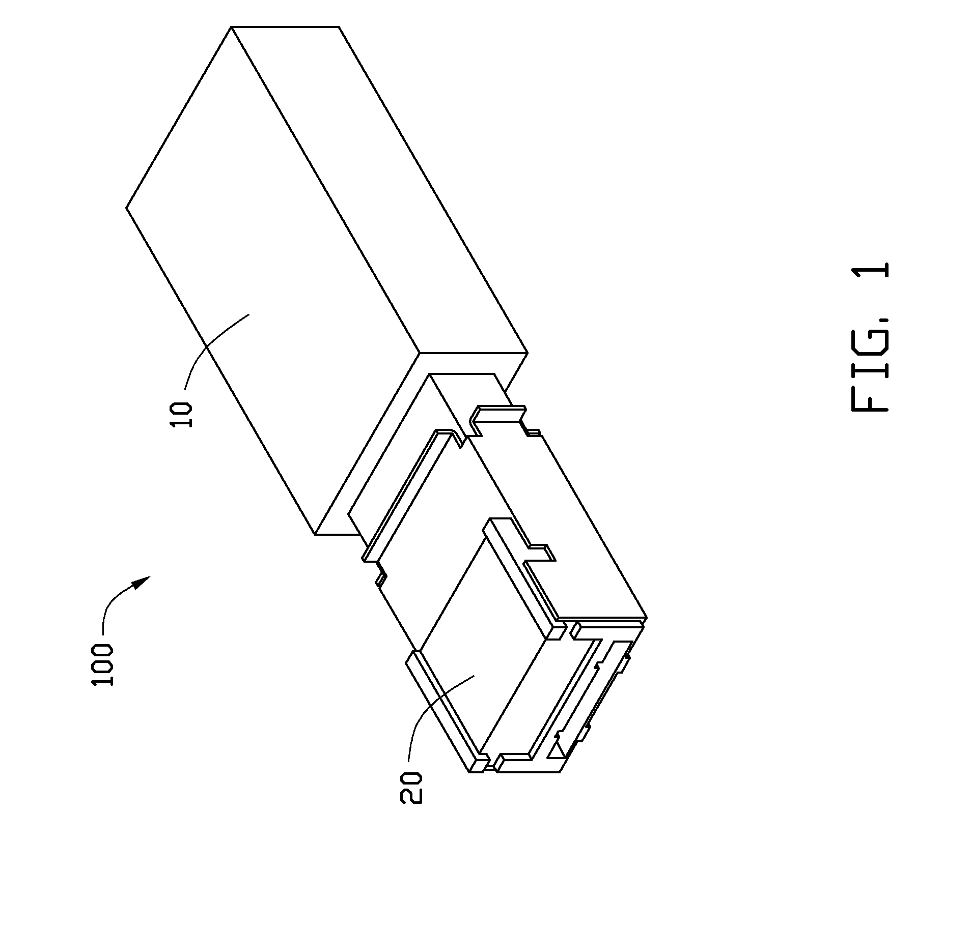
[0017]Referring to FIG. 1, an optical fiber coupling assembly 100, according to a first exemplary embodiment, includes a male optical connector 10 and a female optical connector 20. For example, the female optical connector 20 may be assembled in electronic devices (not shown), such as printers, cameras, and computer hosts. The male optical connector 10 may be assembled to some portable electronic devices or computer peripherals and is coupled to the female optical connector 20 for transmitting optical signals.

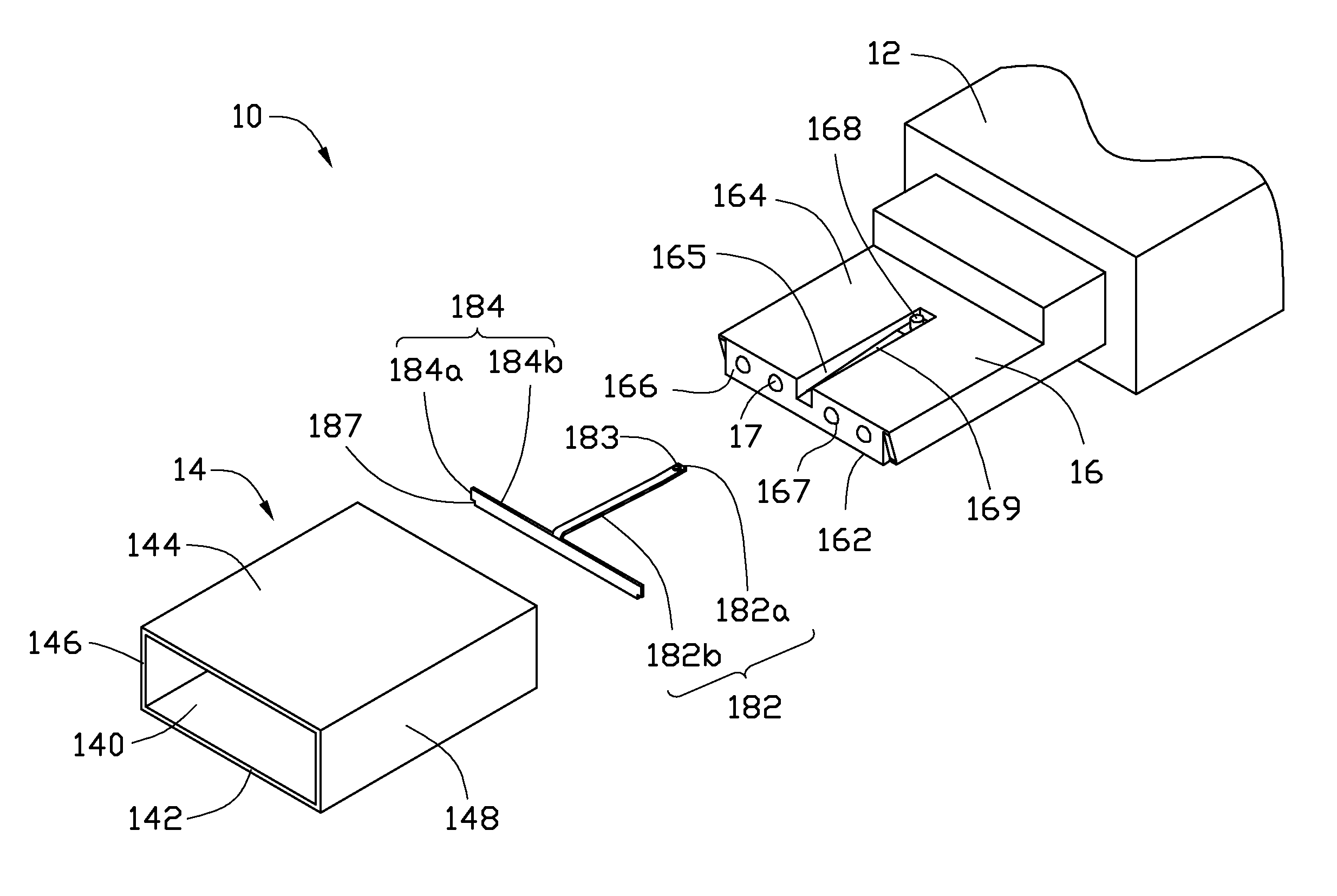
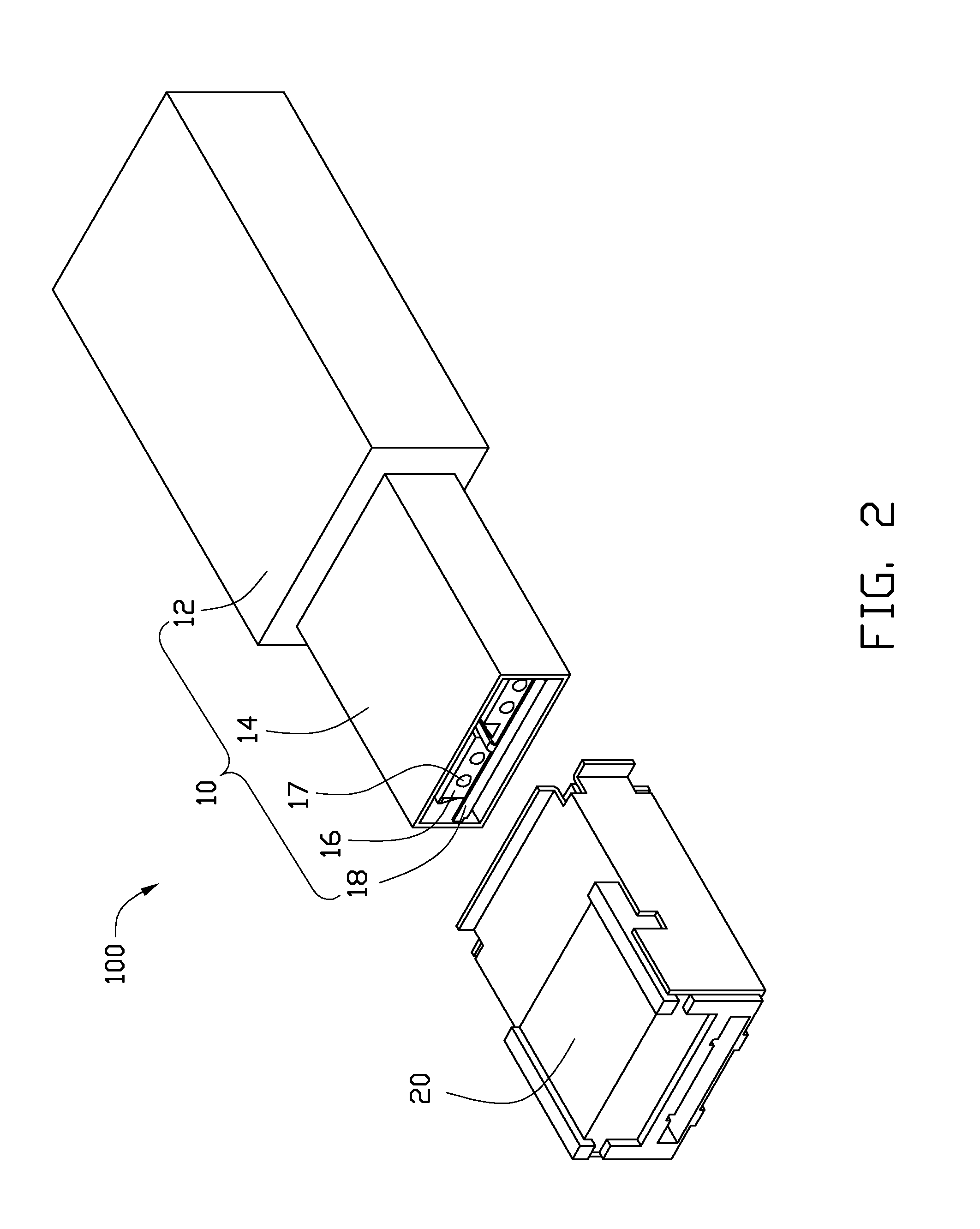
[0018]Referring to FIGS. 2-3, the male optical connector 10 includes a grip 12, an inserting portion 14, an insulative base 16, four first lenses 17, and a cover 18.

[0019]The grip 12 is configured for being held by a user while the male optical connector 10 is coupled to the female optical connector 20.

[0020]The inserting portion 14 is a hollow substantially cuboid and defines a first cavity 140. The inserting portion 14 is attached to the grip 12 and includes a first sidewall...


PUM


Abstract

An optical fiber coupling assembly includes a male optical connector and a female optical connector. The male optical connector includes an insulative base having a first surface, a second surface opposite to the first surface, and a male transmitting surface, first lenses mounted to the insulative base and exposed at the male transmitting surface, and a cover having an arm and a blocking plate. One end of the arm is fixed to the second surface, the other end of the arm resiliently attached to the blocking plate. The blocking plate is apart from the first lenses for covering the first lenses. The female optical connector faces the male transmitting surface. The female optical connector includes an insulative supporting member having a female transmitting surface facing the male transmitting surface, second lenses mounted to the female transmitting surface, and two spaced pushing members formed on the female transmitting surface.

Description

BACKGROUND[0001]1. Technical Field[0002]The present disclosure relates to optical technology and, particularly, to a male optical connector, a female optical connector, and a related optical fiber coupling assembly.[0003]2. Description of Related Art[0004]Currently, an optical fiber coupling assembly is preferred for use in data transmission between electronic devices due to their high transmission speed and signal integrity. Generally, the optical fiber coupling assembly includes two optical fiber connectors, such as a male optical connector and a female optical connector, for coupling the optical fibers together to allow optical transmittance between the optical fibers. The connectors include lenses each being aligned with a corresponding optical fiber. When coupling connectors together, a lens in the male optical connector is aligned with a corresponding lens in the female optical connector to ensure the optical transmittance. However, when the connector is detached from the othe...

Claims


Application Information

Patent Timeline
Patent Type & Authority Patents(United States)
IPC IPC(8): G02B6/38
CPCG02B6/3885G02B6/32G02B6/3849G02B6/3897G02B6/4292
Inventor WU, KUN-CHAN
Owner HON HAI PRECISION IND CO LTD
Why Eureka
Try Eureka