Compact load balanced switching structures for packet based communication networks

a packet-based communication network and load-balancing technology, applied in the field of communication, can solve the problems of network operators seeking an alternative architecture, small delay, and relatively slow bandwidth allocation to accommodate demand

Inactive Publication Date: 2012-08-28
HALL TREVOR DR
View PDF10 Cites 7 Cited by
  • Summary
  • Abstract
  • Description
  • Claims
  • Application Information

AI Technical Summary

Benefits of technology

[0015]As a result the switching node can meet all of the demands of the network provider in terms of quality of service, flexibility of provisioning to a users varied demands for services, and prioritizing packet data switching based upon predetermined priorities of the packets and the dynamic bandwidth allocation between input and output ports. The control approach allows this to be achieved in an architecture where the loading of activities such as switching, memory queuing etc is balanced across the node.

Problems solved by technology

For example, when downloading most information via the Internet, a small delay is acceptable for text and photographs but not for streamed video unless sufficient memory buffer exists.
Within this mesh are a limited number of optical switches which generally provide protection switching and relatively slow allocation of bandwidth to accommodate demand.
But the demands from users for increased services, increased bandwidth and flexible services are causing the network operators to seek an alternative architecture.
Delay—the time taken to route packets across the network, where excessive delay in any single packet of a message prevents the message being completed
Mis-Sequencing—the mis-sequencing of packets through the network causes delays at the user as until the mis-sequenced packet arrives the message cannot be completed
Losses—the loss of packets due to blocked connections within the network causes delays as the lost packets must be retransmitted across the network.

Method used


Image

  • Compact load balanced switching structures for packet based communication networks
  • Compact load balanced switching structures for packet based communication networks
  • Compact load balanced switching structures for packet based communication networks

Examples


exemplary first embodiment

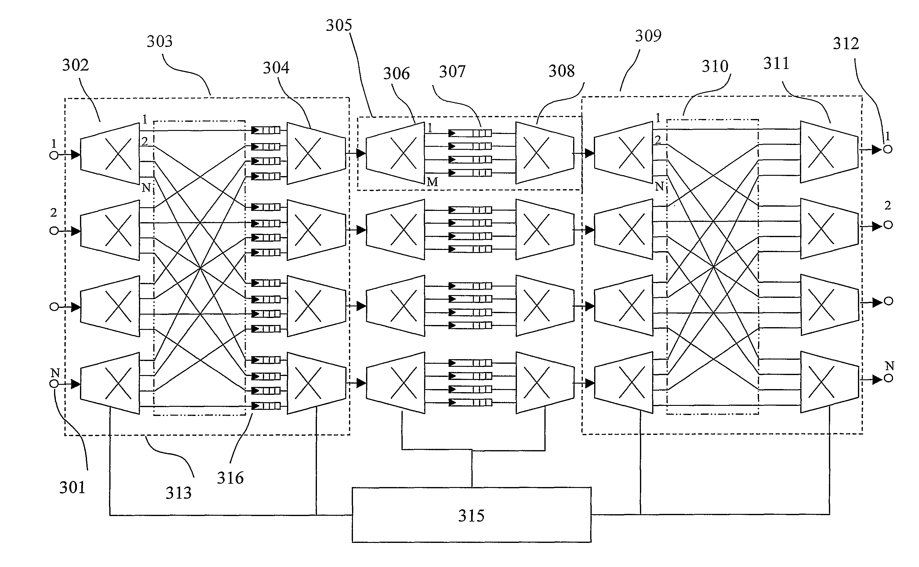
[0030]Referring to FIG. 3A, the invention is shown in the form of a compact load balanced crossbar packet switch with queued input ports. Here a packet of data is incident at one of the input ports 301 of the packet switching node. The header of the packet is read and communicated to the packet switching node controller 315 which defines the appropriate routing of the packet through the node. The packet switching controller 315 communicates routing data to the first stage switch matrix 303 comprising a first N×N crossbar switch with memory queues. This is implemented using 1:N distribution switches 302, a perfect shuffle 313, a plurality of memory queues 316 and N:1 concentrator switches 304. The packet of data exits the first stage switching matrix 303 on a link connecting a second stage switch matrix 305 determined by the packet switching node controller 315.

[0031]The second stage switch matrix 305 is constructed from 1:M distribution switches 306, M memory queues 307, and M:1 con...


PUM


Abstract

A switching node is disclosed for the routing of packetized data employing a multi-stage packet based routing fabric combined with a plurality of memory switches employing memory queues. The switching node allowing reduced throughput delays, dynamic provisioning of bandwidth and packet prioritization.

Description

[0001]This application claims the benefit of U.S. Provisional Application No. 60 / 636,485, filed Dec. 17, 2004.FIELD OF THE INVENTION[0002]The invention relates to the field of communications and more particularly to a scaleable architecture for packet based communication networking.BACKGROUND OF THE INVENTION[0003]Telecommunications networks have evolved from the earliest networks having few users with plain old telephone service (POTS) to networks in operation today interconnecting hundreds of millions of users with a wide variety of services including for example telephony, Internet, streaming video, and MPEG music. Central to these networks is the requirement for a switching fabric allowing different users to be connected either together or to a service provider. Supporting an increase in a number of users, connections and bandwidth are networks based upon segmentation, transmission, routing, detection and reconstruction of a signal. The segmentation results in a message being di...

Claims


Application Information

Patent Timeline
Patent Type & Authority Patents(United States)
IPC IPC(8): H04L12/56H04L12/54
CPCH04L47/125H04L49/101H04L49/3018H04L49/90
Inventor HALL, TREVORPAREDES, SOFIATAEBI, SAREH
Owner HALL TREVOR DR
Why Eureka
Try Eureka