Low-Noise, High-Speed, High Precision and High-Thrust Flux Reversal Motor for Linear or Rotary Motion System

Active Publication Date: 2009-01-08
KOREA ELECTROTECH RES INST
View PDF3 Cites 30 Cited by
  • Summary
  • Abstract
  • Description
  • Claims
  • Application Information

AI Technical Summary

Benefits of technology

[0005]Accordingly, the present invention has been made keeping in mind the above problems occurring in the prior art, and the present invention is directed to provide a flux reversal linear motor, which can reduce the manufacturing cost thereof because the number of permanent magnets that are used is decreased, which can facilitate magnetization by enabling movable permanent magnets, having the same polarities, to be provided in a

Problems solved by technology

However, a conventional permanent magnet linear synchronous motor is formed to have an actuation coil structure, in which permanent magnets are located in a stator, so that it has disadvantages in that the manufacturing cost thereof is inevitably increased because the movement distance is increased and, thus, the number of permanent magnets that are used is increased, and in t

Method used


Image

  • Low-Noise, High-Speed, High Precision and High-Thrust Flux Reversal Motor for Linear or Rotary Motion System
  • Low-Noise, High-Speed, High Precision and High-Thrust Flux Reversal Motor for Linear or Rotary Motion System
  • Low-Noise, High-Speed, High Precision and High-Thrust Flux Reversal Motor for Linear or Rotary Motion System

Examples


Embodiment Construction

[0048]Preferred embodiments of the present invention are described in detail below with reference to the accompanying drawings and details described in the accompanying drawings, but the present invention is not limited to the embodiment, and is not to be defined by the embodiments. The same reference numerals, which are used throughout the different drawings, designate the same or similar components.

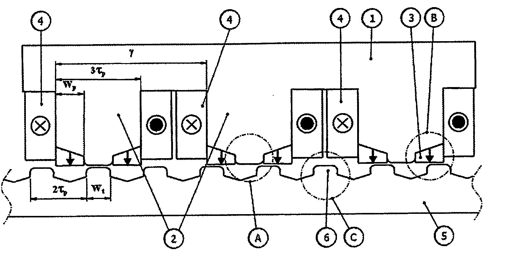
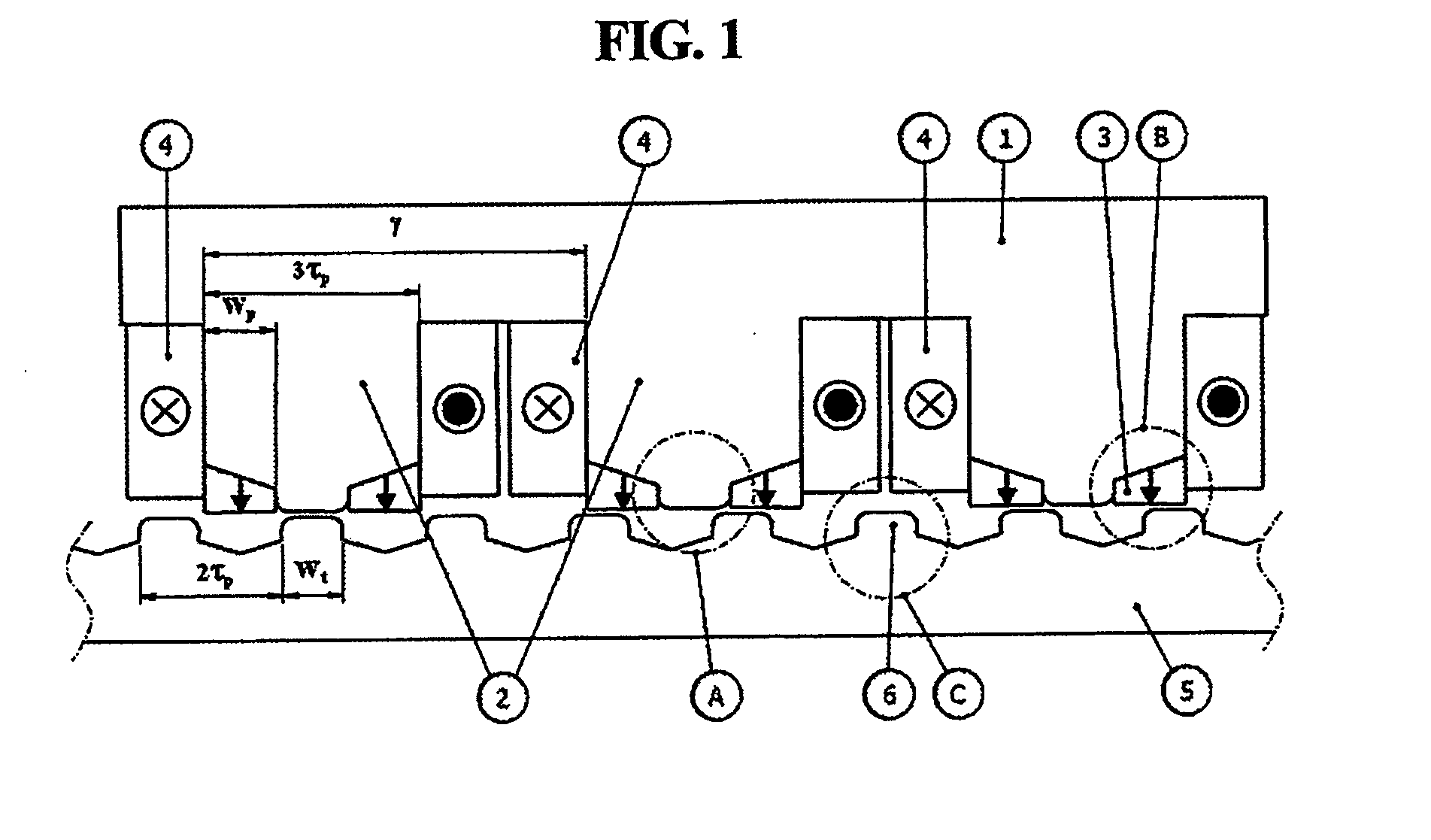
[0049]FIG. 1 is a view illustrating the mover and stator of a linear motor according to an embodiment of the present invention. Referring to FIG. 1, the mover of the linear motor according to the embodiment of the present invention includes a mover core 1, mover teeth 2, permanent magnets 3, and mover phase coils 4. The stator of the linear motor according to the embodiment of the present invention includes a stator core 5 and stator teeth 6.

[0050]When an appropriate amount of current is applied to the mover phase coils 4, which are formed by winding the coil around the mover teeth 2, a...


PUM


Abstract

Disclosed herein is to a flux reversal motor. The flux reversal motor includes a mover, and a plurality of permanent magnets. The mover moves linearly relative to a stator. A plurality of permanent magnets, having identical polarities, is provided in the end of each mover tooth. The permanent magnets are arranged on the left and right sides of a protrusion of the end of the mover tooth. Thus low noise/low vibration, high speeds, high precision, and high thrust motion can be realized.

Description

BACKGROUND OF THE INVENTION[0001]1. Field of the Invention[0002]The present invention relates generally to a flux reversal motor and, more particularly, to a linear motor, which can decrease the number of permanent magnets that are used, can facilitate magnetization using permanent magnets having the same polarities, can move at high speed because thrust is increased, and can realize low noise / low vibration and high precision position control by decreasing the pulsation of thrust and normal force, and to a rotary motor, which is based on the concept of the linear motor, and which can prevent the degradation of the permanent magnets from occurring because the permanent magnets are provided in a rotor, can prevent scattering from occurring because the permanent magnets are provided in a stator, and can be effectively manufactured by applying divided iron cores to a stator or rotor.[0003]2. Description of the Related Art[0004]A conventional linear motor representatively includes a perm...

Claims


Application Information

Patent Timeline
IPC IPC(8): H02K37/02H02K41/03
CPCH02K1/148H02K1/246H02K21/20H02K2213/03H02K21/44H02K41/033H02K21/22
Inventor CHUNG, SHI UKKANG, DO HYUNCHANG, JUNG HWANKIM, JI WONLEE, JI YOUNG
Owner KOREA ELECTROTECH RES INST
Why Eureka
Try Eureka