Coupling device for media conduits

a technology of coupling device and media conduit, which is applied in the direction of railway coupling, towing device, screws, etc., can solve the problems of difficult installation and other problems, and achieve the effect of reducing the risk of detachment and compensating play

Inactive Publication Date: 2012-09-04
VOSS AUTOMOTIVE
View PDF14 Cites 5 Cited by
  • Summary
  • Abstract
  • Description
  • Claims
  • Application Information

AI Technical Summary

Benefits of technology

[0007]In another embodiment of the invention, each coupling part also has substantially identical means, firstly, for securing it to an installation wall and, secondly, for the mutual connection to the respectively other coupling part. The two holding connections advantageously take place with the use of self-tapping or self-thread-forming screws which are each screwed directly into initially smooth-walled holes (also sometimes referred to as “blind holes”) of the respective coupling part. This also renders special threaded inserts superfluous. The screw fastening to the installation wall achieves secure fixing which eliminates the risk of detachment during the coupling operation. In addition, compensation for play is no longer required.

Problems solved by technology

In addition, the installation is also sometimes difficult because the fixing of the one coupling plate merely by latching (pre-fixing) during the coupling operation is often not sufficiently secure, and therefore the coupling plate may be detached from the installation wall during the joining operation of the other coupling plate if it is not additionally secured manually, but this is not always possible depending on the fitting situation.

Method used


Image

  • Coupling device for media conduits
  • Coupling device for media conduits
  • Coupling device for media conduits

Examples


Embodiment Construction

[0023]In order that the present invention may be more readily understood, embodiments thereof will now be described, with reference to the accompanying drawings. The following description is merely exemplary in nature and is in no way intended to limit the invention or its application or uses.

[0024]In the various figures of the drawing, identical parts are provided with the same reference numbers. Each description of a part, which is possibly only undertaken once with reference to one of the figures of the drawing, applies analogously with respect to the other figures of the drawing in which that part can likewise be seen with the corresponding reference number.

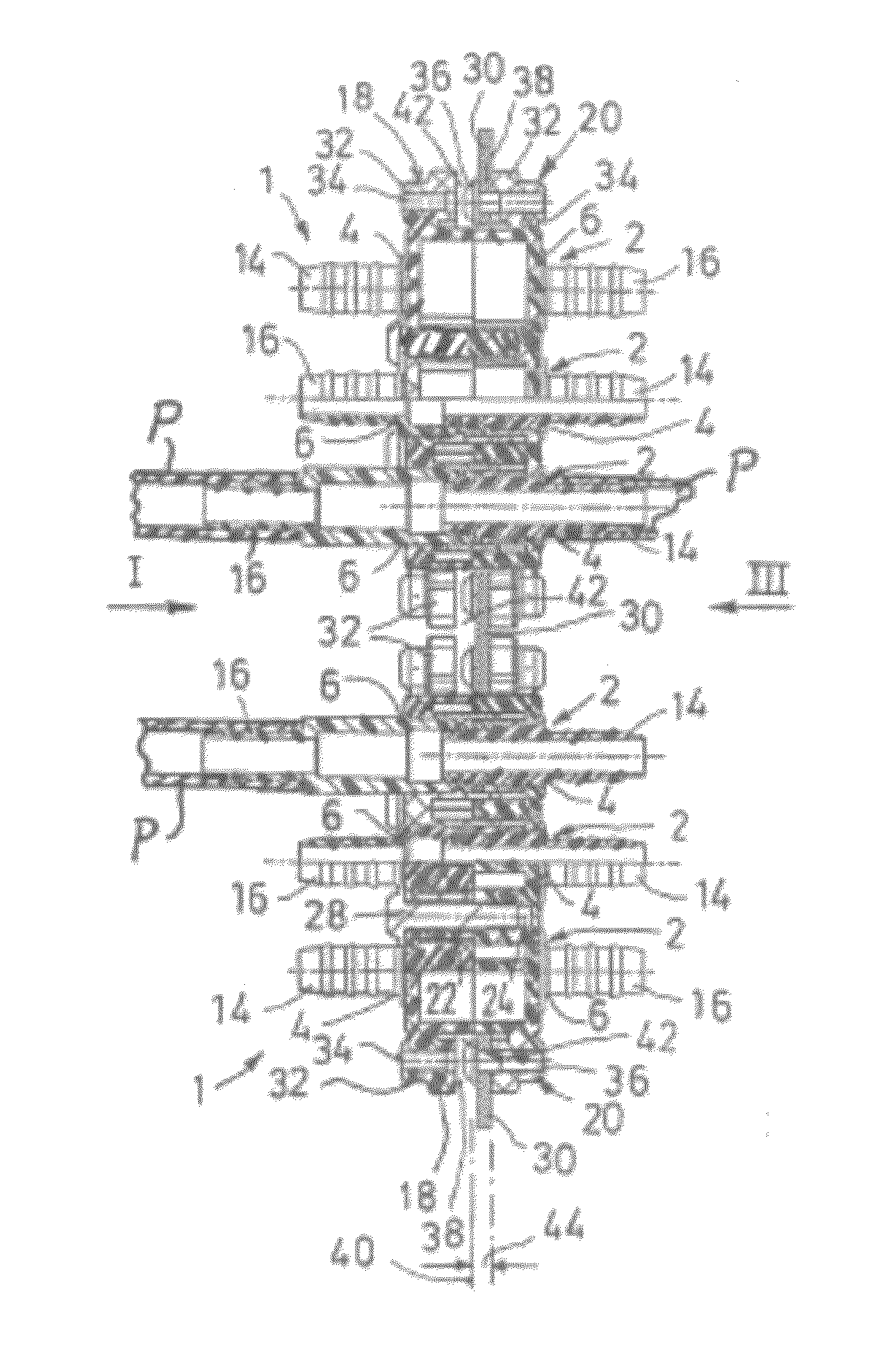
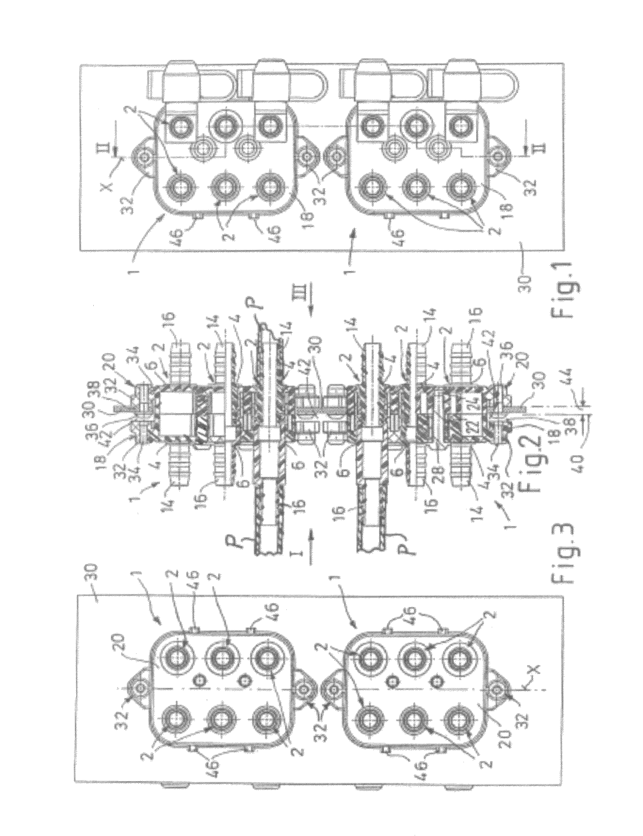
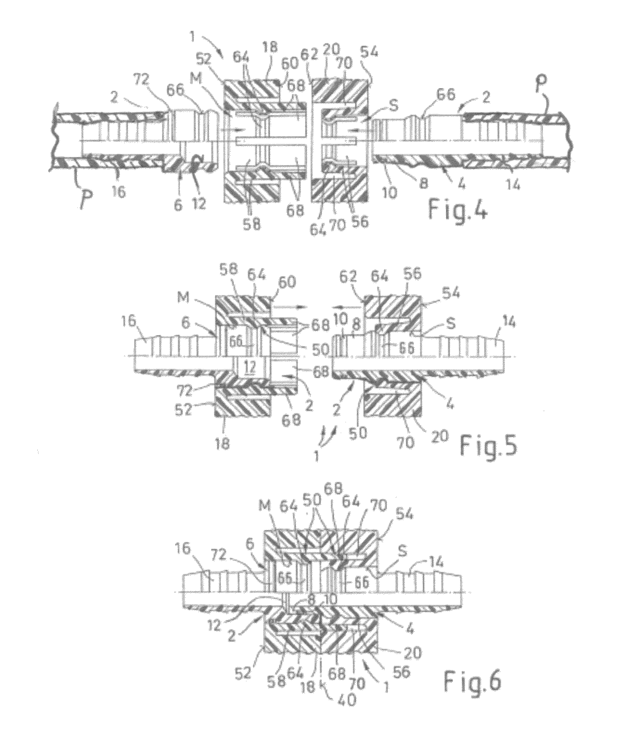
[0025]A coupling device 1 according to the invention is provided for an even number of at least two, and in the illustrated embodiment six, plug-in couplings 2. The coupling device comprises two plug-in coupling parts, a plug part 4 and a socket part 6. As best seen in FIGS. 4-6, each plug part 4 has a plug stem 8 which can b...


PUM


Abstract

A coupling device for tubes and / or pipes comprising two substantially identical plate-type coupling parts is provided. Each coupling part has an even number of openings to receive inserted plug-in couplings configured as plug parts or socket parts. In one embodiment, the receiving openings for plug parts are arranged mirror-symmetrically across an axis of symmetry from the receiving openings for socket parts. The plug and socket parts are joined by first inserting and securing them into their respective receiving openings in the two coupling parts, then connecting the coupling parts.

Description

CROSS REFERENCE TO RELATED APPLICATION[0001]This application claims priority to PCT / EP2006 / 050413, filed 24 Jan. 2006 and DE 20 2005 001 153.3, filed 24 Jan. 2005.BACKGROUND OF THE INVENTION[0002]The present invention relates to a coupling device for tubes and / or pipes, in particular for wall ducts of flow media conduits. The device has two plate-type coupling parts which can be connected to each other in a parallel arrangement, with each having receiving openings for the insertion and for the fixed securing of plug-in coupling parts, more precisely plug parts and socket parts, in such a manner that, by connection of the coupling parts, the plug and socket parts are plugged one into the other in pairs in a joining direction.[0003]Coupling devices of this general type, including devices having some of the features described in EP 0618393 A1 / B1, have been in practical use in an embodiment as a multiple coupling, for example, being used for a conduit duct in the region of an installati...

Claims


Application Information

Patent Timeline
Patent Type & Authority Patents(United States)
IPC IPC(8): F16L39/00
CPCF16L5/14F16L37/098F16L37/56F16L5/12
Inventor HAGEN, HARALDBRANDT, JOSEF
Owner VOSS AUTOMOTIVE
Why Eureka
Try Eureka