
Illumination device

a technology of a slitting device and a slitting plate, which is applied in the direction of lighting and heating apparatus, slitting support devices, fixed installations, etc., can solve the problems of high material cost and high manufacturing cost, and cannot be easily disassembled and assembled during maintenance, so as to increase the number of light emitting components, and facilitate assembly and disassembly. , the effect of easy replacemen

Active Publication Date: 2012-09-04
LEOTEK CORP
View PDF28 Cites 43 Cited by
  • Summary
  • Abstract
  • Description
  • Claims
  • Application Information

AI Technical Summary

Benefits of technology

"The present invention provides an illumination device with a lamp housing component, a main bone, and at least one light emitting component. The light emitting component has a heat sink member and a light emitting member. The main bone is connected to the lamp housing component and the light emitting member contacts the heat sink member. The light emitting member further comprises a circuit board, at least one LED, and a secondary optical member. The efficacy of the present invention is that the number of light emitting components can be increased or decreased based on the demand for luminance, and if one of the light emitting components fails, it can be easily disassembled and replaced with a new one."

Problems solved by technology

Currently, a road lamp is configured with a heat-sink lamp housing manufactured by die casting, which has a high material cost and a high manufacturing cost.
The light emitting components (for example, LED elements) are directly locked on the heat-sink lamp housing, and cannot be easily disassembled and assembled during maintenance.

Method used


Image

  • Illumination device
  • Illumination device
  • Illumination device

Examples


Embodiment Construction

[0024]To make the objectives, structures, features, and functions of the present invention more comprehensible, the present invention is illustrated below in detail through the embodiments.

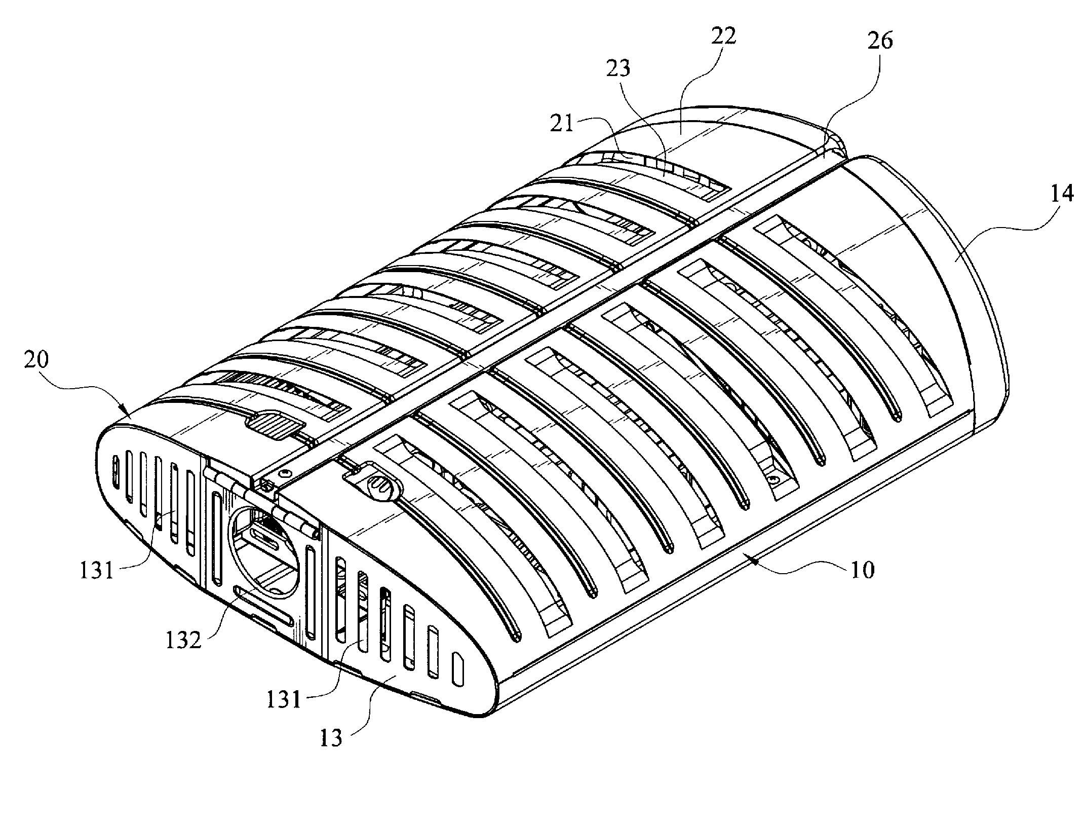
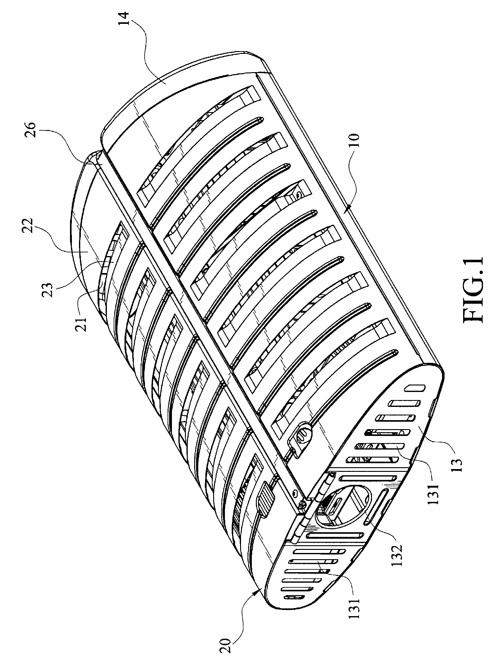
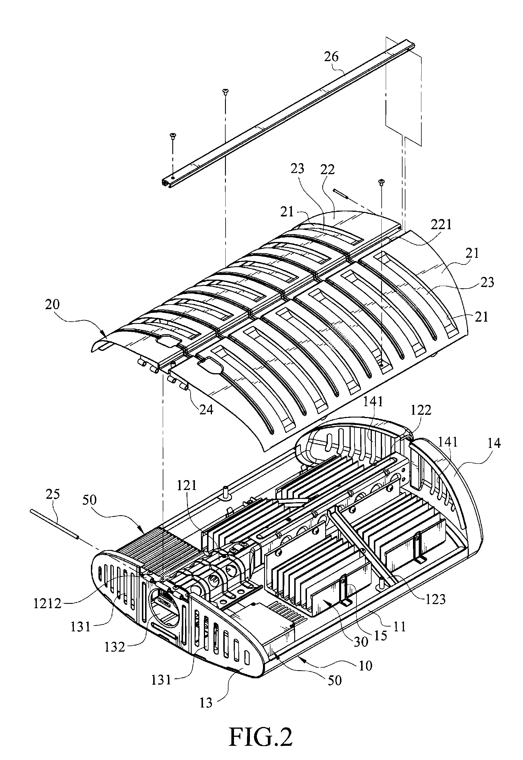
[0025]FIG. 1 is a schematic outside view of an embodiment of the present invention, FIG. 2 is a schematic partially exploded view of an embodiment of the present invention, and FIG. 3 is a schematic exploded view of an embodiment of the present invention. As shown in FIGS. 1, 2, and 3, an illumination device disclosed in the present invention substantially comprises a lamp housing component and a light emitting component.

[0026]The lamp housing component has a lamp base 10 and a lamp shade 20. The lamp base 10 comprises a case 11, a main bone 12, and two side plates 13 and 14. The case 11 has a bottom surface 111 (as shown in FIG. 7) and is opened with at least one accommodation hole 113 and a plurality of first air-inlet holes 114. The accommodation holes 113 are provided for assembling and positi...


PUM


Abstract

An illumination device includes a lamp housing component, a main bone disposed inside the lamp housing component, and at least one light emitting component. The light emitting component has a heat sink member and a light emitting member. The heat sink member is locked on the main bone, and the light emitting member is disposed on the lamp housing component and contacts the heat sink member. According to the demand for luminance, the number of light emitting components is optionally increased or decreased on the main bone, or the main bone inside the lamp housing component is replaced by an extended main bone, so as to increase the number of light emitting components.

Description

BACKGROUND OF THE INVENTION[0001]1. Field of Invention[0002]The present invention relates to an illumination device, and more particularly to an illumination device having an expandable structure, which has desirable heat dissipation effects and is easily maintained.[0003]2. Related Art[0004]Currently, a light emitting diode (LED) has already been used on a road lamp for illumination. The LED has advantages of a low power consumption, high luminance, and long lifetime, and thus can solve the problems such as a high power consumption and short lifetime of a conventional mercury road lamp. However, when the LED is applied to the road lamp, the problem of poor heat dissipation still occurs, and the high-temperature heat source generated by the LED causes the heats to be accumulated inside the lamp. As a result, the circuit substrates or electronic devices are damaged due to being overheated.[0005]Therefore, a heat dissipation device is needed to divert the high-temperature heat source ...

Claims


Application Information

Patent Timeline
Patent Type & Authority Patents(United States)
IPC IPC(8): F21V29/00
CPCF21V29/83F21V17/107F21V29/004F21V29/507F21V29/71F21V29/75F21V29/76F21S8/086F21K9/00F21V5/007F21V15/015F21V19/04F21W2131/103F21Y2101/02F21Y2105/001F21V29/74F21Y2105/10F21Y2115/10
Inventor HU, SHENG-HSIUNGYEH, YU-YUANWU, MING-CHUNLEE, CHING-PO
Owner LEOTEK CORP
Learn More