
Stent/graft assembly

a technology of grafts and stents, applied in the field of stents and grafts, can solve the problems of occlusion, emboli production, prone to aneurysms, etc., and achieve the effect of simple deployment of endovascular grafts, easy releasability, and small cross sectional dimension

Inactive Publication Date: 2012-09-04
KERR ANDREW
View PDF35 Cites 21 Cited by
  • Summary
  • Abstract
  • Description
  • Claims
  • Application Information

AI Technical Summary

Benefits of technology

The endovascular graft assembly achieves a smaller cross-sectional dimension, allowing for easier insertion and deployment, reducing the need for additional stent expansion and simplifying the surgical procedure while providing enhanced fixation and prevention of graft drift in the blood vessel.

Problems solved by technology

The aorta is prone to aneurysms.
Aortic aneurysms that are not treated in a timely manner can lead to rupture, occlusion, infection or the production of emboli which can flow downstream and occlude a smaller blood vessel.
A ruptured aortic aneurysm typically is fatal due to a loss of the large volume of blood that flows through the abdominal aorta.
However, the coaxially and longitudinally coextensive arrangement of the stent and graft has resulted in a cross-sectionally large assembly.
A cross-sectionally large graft and stent assembly can be difficult to insert and deliver intravascularly to the damaged section of the blood vessel and may require surgery.

Method used


Image

  • Stent/graft assembly
  • Stent/graft assembly
  • Stent/graft assembly

Examples


first embodiment

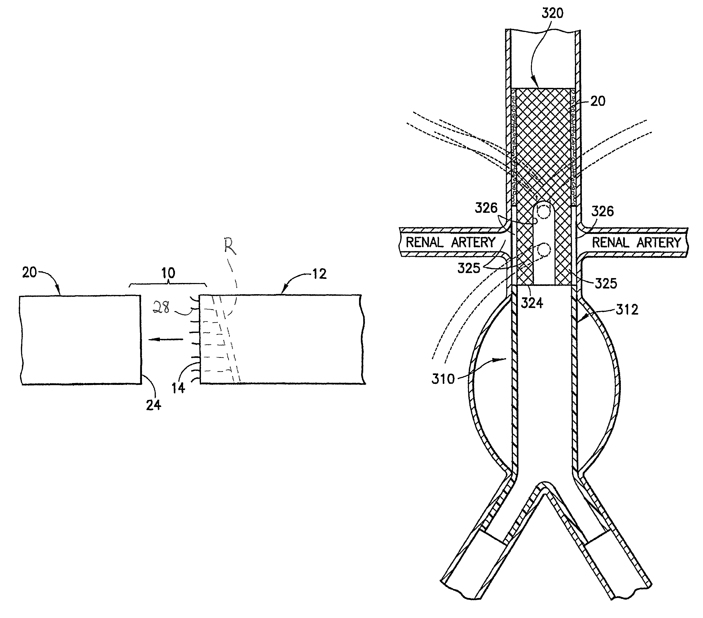
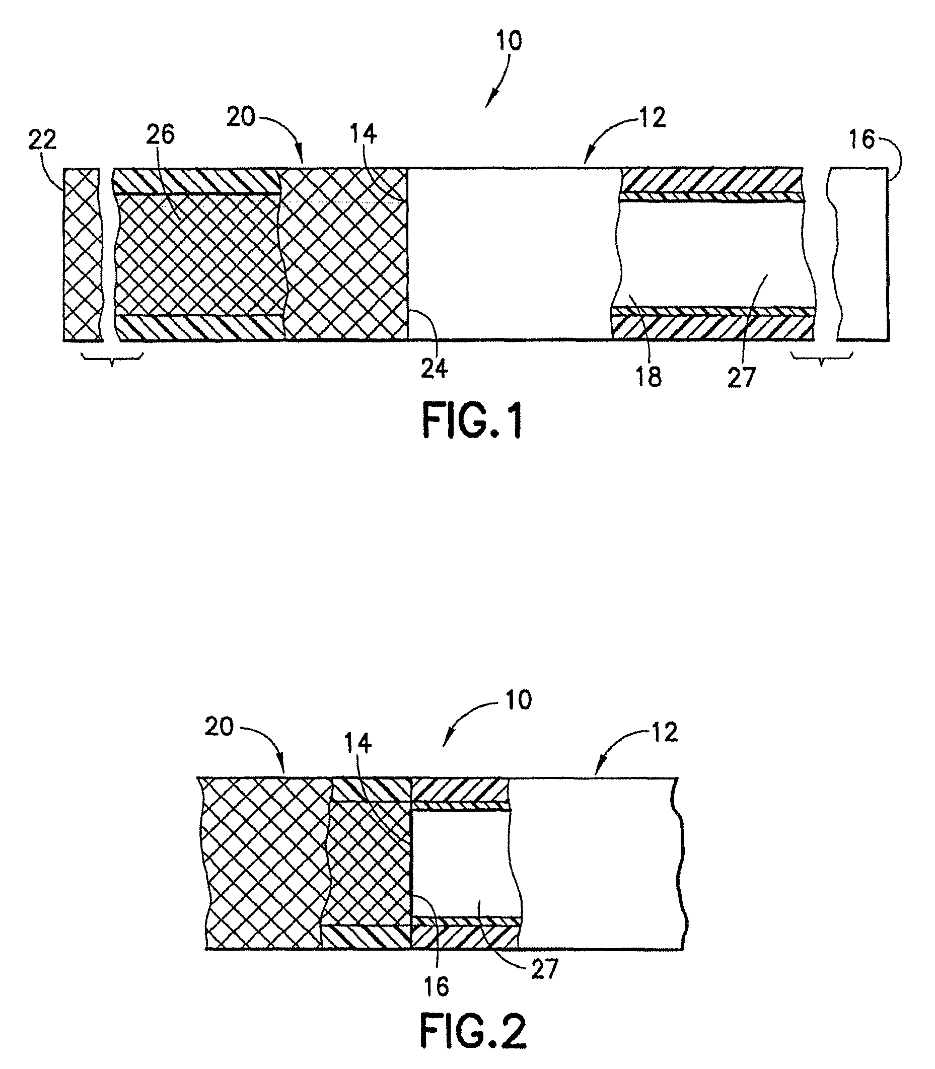
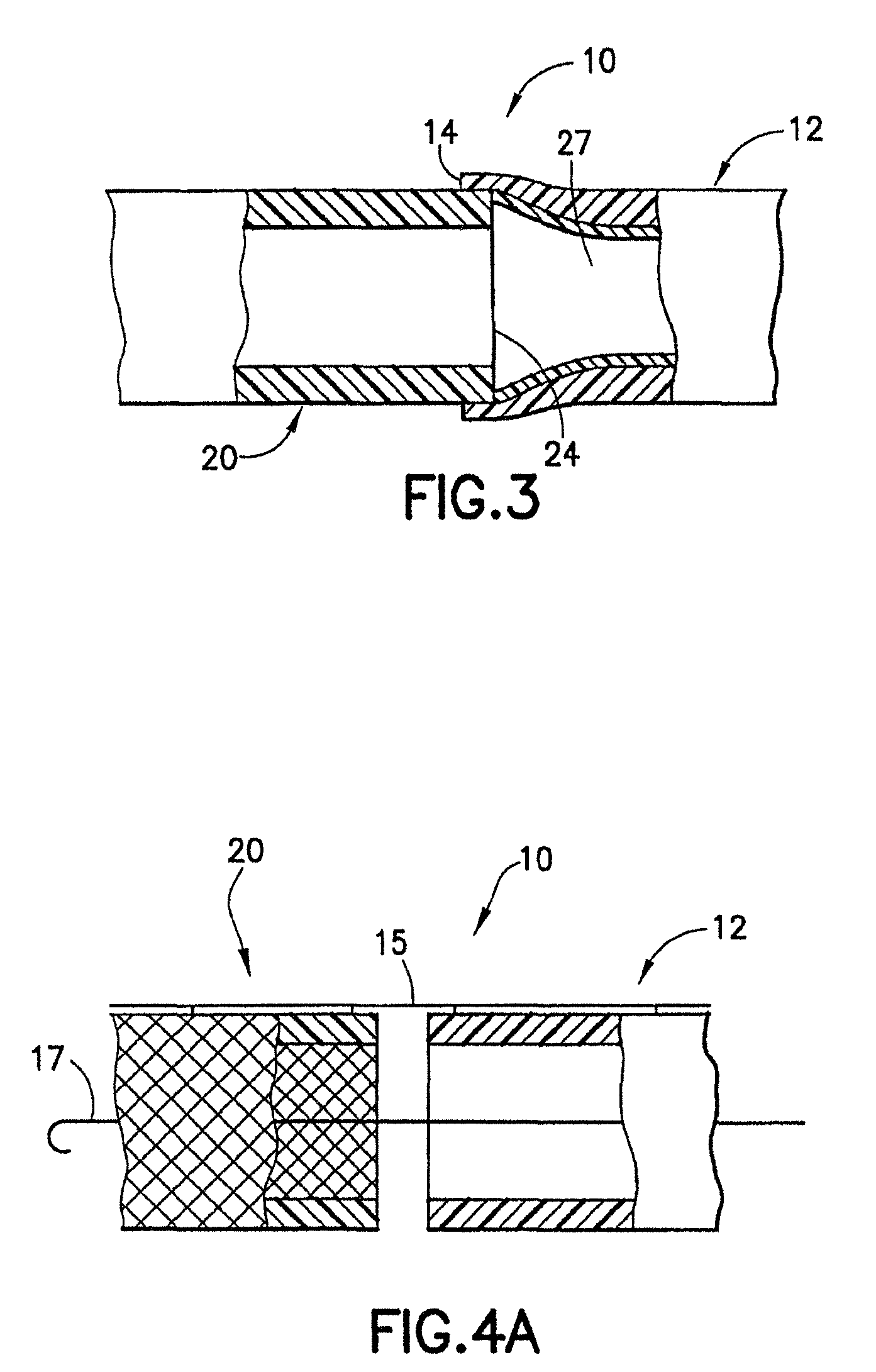
[0080]An endovascular stent / graft assembly in accordance with the invention is identified generally by the numeral 10 in FIG. 1. The endovascular stent / graft assembly 10 includes a substantially tubular graft 12 having a flexible wall formed from a synthetic material, such as a polyester material that is substantially impervious to fluid transmission or that becomes substantially impervious after exposure to blood. The tubular graft 12 has an upstream end 14, a downstream end 16 and a fluid passage 18 extending between the ends. The endovascular stent / graft assembly 10 further comprises a tubular stent 20 having an upstream end 22, a downstream end 24 and a passage 26 extending between the ends. The tubular stent 20 may be of known construction and may be formed from materials that are known to those skilled in the art of treating vascular anomalies with endovascular stent / graft assemblies, such as polyethylene terepthalate and PTFE, including materials sold under the trademarks DAC...

second embodiment

[0088]FIG. 7 shows an endovascular stent / graft assembly 32 in accordance with the invention. The endovascular stent / graft assembly 32 includes a tubular graft 12 substantially identical to the tubular graft 12 in the embodiment of FIG. 1. The stent / graft assembly 32 further includes an upstream tubular stent 20 substantially identical to the tubular stent 20 in the embodiment of FIG. 1. However, the stent / graft assembly 32 further includes a downstream stent 34. The downstream stent 34 has an upstream end 36, a downstream end 38 and a tubular passage 40 extending between the ends. The upstream end 36 of the downstream stent 34 is connected in substantially end-to-end relationship with the downstream end 16 of the tubular graft 12 by any of the connection arrangements depicted respectively in FIGS. 2-6. The downstream stent 34 can be connected to the tubular graft prior to insertion of the stent / graft assembly 32 into the blood vessel. Alternatively, the sub-assembly of the tubular g...

fourth embodiment

[0092]the endovascular stent / graft assembly is identified by the numeral 50 in FIG. 12. The endovascular stent / graft assembly 50 is a variation of the stent / graft assembly 46 of FIG. 11 in that a plurality of wires 52 extend axially from the stent 20 substantially to the downstream end 16 of the tubular graft 12 where the wires 52 are affixed to the tubular graft 12. The stent / graft assembly 50 prevents axial collapsing of the tubular stent 20, substantially as with the embodiment of FIG. 11. However, the wires 52 will further provide radially support for the tubular graft 12 and will resist radially collapsing of the graft 12.


PUM


Abstract

A stent / graft assembly includes a tubular graft connected in substantially end-to-end relationship with a generally tubular stent. Free ends of the stent and graft extend in opposite directions from the end-to-end connection during a pre-deployment orientation of the assembly. However, the graft is inverted during deployment so that free ends of the graft and the stent extend in substantially the same direction from the end-to-end connection in a post-deployment orientation. Thus, at least a portion of the stent is disposed within at least a portion of the graft in a post-deployment orientation of the assembly.

Description

CROSS-REFERENCE TO RELATED APPLICATIONS[0001]This application is a divisional of application Ser. No. 12 / 137,632 filed Jun. 12, 2008 now abandoned), which is a divisional of application Ser. No. 10 / 849,652, filed May 20, 2004 (now abandoned), which is a continuation-in-part of application Ser. No. 09 / 900,241 filed Jul. 6, 2001(now U.S. Pat. No. 7,105,017) and a continuation-in-part of application Ser. No. 09 / 961,825 filed Sep. 24, 2001 (now abandoned) and a continuation-in-part of application Ser. No. 10 / 299,882 filed Nov. 19, 2002 (now U.S. Pat. No. 7,175,651) and a continuation-in-part of application Ser. No. 10 / 612,531 filed Jul. 1, 2003 (now abandoned). This application also is a divisional of application Ser. No. 11 / 655,315 filed Jan. 19, 2007 (now abandoned) which is a divisional of application Ser. No. 10 / 299,882 filed Nov. 19, 2002 (now U.S. Pat. No. 7,175,651), which is a continuation-in-part of application Ser. No. 09 / 961,825 filed Sep. 24, 2001 (now abandoned) and which i...

Claims


Application Information

Patent Timeline
Patent Type & Authority Patents(United States)
IPC IPC(8): A61F2/82
CPCA61F2/07A61F2002/067A61F2002/075A61F2002/077A61F2220/0075A61F2002/065A61F2/89A61F2/90A61F2/954A61F2002/91558A61F2002/91583A61F2/82
Inventor KERR, ANDREW
Owner KERR ANDREW
Learn More