Remote-controlled light receiving structure of electric roll screen for blind

a technology of electric roll screen and remote control, which is applied in the direction of door/window protective devices, instruments, curtain suspension devices, etc., can solve the problems of the inability to remotely and the inability to remote control the electric roll screen from a location. achieve the effect of convenient and reliable operation

Inactive Publication Date: 2012-09-04
SHINSEI SEIKI
View PDF4 Cites 40 Cited by
  • Summary
  • Abstract
  • Description
  • Claims
  • Application Information

AI Technical Summary

Benefits of technology

[0006]In the light of these disadvantages, the present invention has been made. It is an object of the present invention to provide a remote-controlled light receiving structure of an electric roll screen for blind which can effect the remote control operation and enhance the convenience effectively, irrespective of installation constraint of the electric roll screen, by improving the inside mounting method wherein the light receiving unit is mounted at the side bracket, in particular.
[0008]In this structure, even when the electric roll screen is set in reverse under interior layout constraint and the like, the light receiving unit can be changed in light receiving direction and thereby it can be oriented toward the inside of the room as normal. Thus, irrespective of the installation constraint of the electric roll screen, the electric roll screen can be remote-controlled by the remote controller even from a location in the room spaced apart from it, thus enhancing convenience. In addition, since the light receiving unit is only switched in two directions to change or switch the light receiving direction, the structure for the direction change can be relatively simplified, thus facilitating to practice.
[0010]In this structure, since the motor is placed in the take-up pipe and also is supported by the side bracket through the limit case, the side bracket can be reduced in thickness, as compared with the structure wherein the motor is mounted on the side bracket. This can contribute to installation-space-saving and thus enhancement of versatility.
[0012]In this structure, since the light receiving unit holder is rotatably mounted on the bracket cover fixed to the outside surface of the side bracket and also the light receiving unit held by that light receiving unit holder is structured so that it can constantly receive a pulsed optical signal applied from the remote controller through the transparent, circular-arc-shaped, light receiving unit cover mounted on the lower end of the bracket cover, irrespective of the change of the light receiving direction, the light receiving unit can be protected by the light receiving unit cover. Also, sensitivity of the light receiving unit can be prevented from being varied by the change in the light receiving direction of the light receiving unit, thus enhancing reliability.
[0014]In this structure, the light receiving direction of the light receiving unit can be easily switched with for example a driver and the like which is inserted in the operating slot formed in the one end surface of the light receiving unit holder extending through the fitting hole of the bracket cover and facing outside and is operated rotationally, thus contributing to simplification of the installation operation.
[0016]In this structure, when the light receiving direction of the light receiving unit is switched by rotationally operating the light receiving unit holder fitted in the fitting hole of the bracket cover, the projecting portion on the bracket cover side is held in sandwich relation by the first holding lug and the second holding lug of the holding portion located on the light receiving unit holder side and thereby the light receiving direction of the light receiving unit switched is maintained. Thus, the direction change operation of the light receiving unit can be done easily and reliably, thus providing a beneficial effect for putting the present invention into practice.

Problems solved by technology

Of these conventional mounting methods, the inside mounting method has the disadvantage that the electric roll screen cannot be remote-controlled with the remote controller, depending on orientations of the light receiving unit.
For example, in the case where the light receiving unit is mounted on a lateral end of the side bracket, when the electric roll screen is set with the light receiving unit orientated toward an inside of a room, no remote-control-operation problem is presented, but when the electric roll screen is set with the light receiving unit orientated toward a wall of the room under interior layout constraint and the like, it cannot be remote-controlled with the remote controller.
Also, when the light receiving unit is mounted on a lower end surface of the side bracket, the electric roll screen cannot be remote-controlled from a location apart from the window of the building where the electric roll screen is mounted.
On the other hand, the outside mounting method involves the mounting of the light receiving unit and the connection of wires between the light receiving unit and a control panel fixed to the mounting frame and the like, thus involving the problems that it takes a lot of time and labor with the mounting and wiring works and also the appearance is spoiled by the wires.

Method used


Image

  • Remote-controlled light receiving structure of electric roll screen for blind
  • Remote-controlled light receiving structure of electric roll screen for blind
  • Remote-controlled light receiving structure of electric roll screen for blind

Examples


Embodiment Construction

[0034]In the following, an embodiment of the present invention which is a best mode for carrying out the invention will be described with reference to the accompanying drawings.

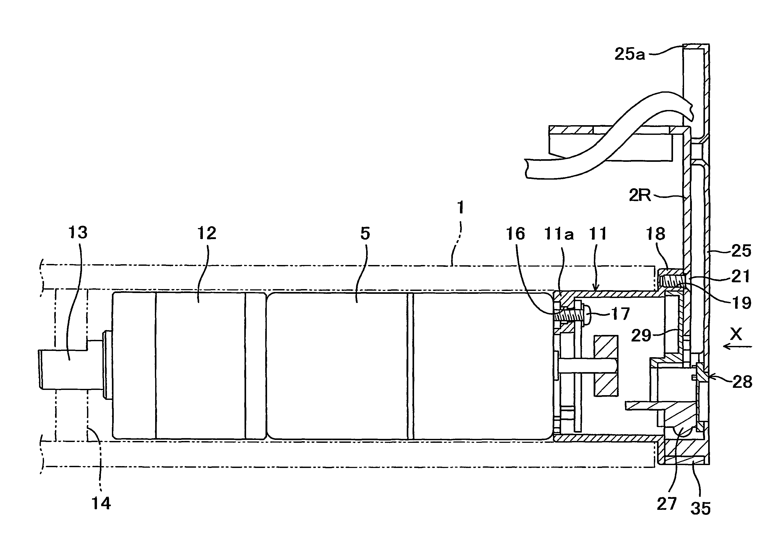
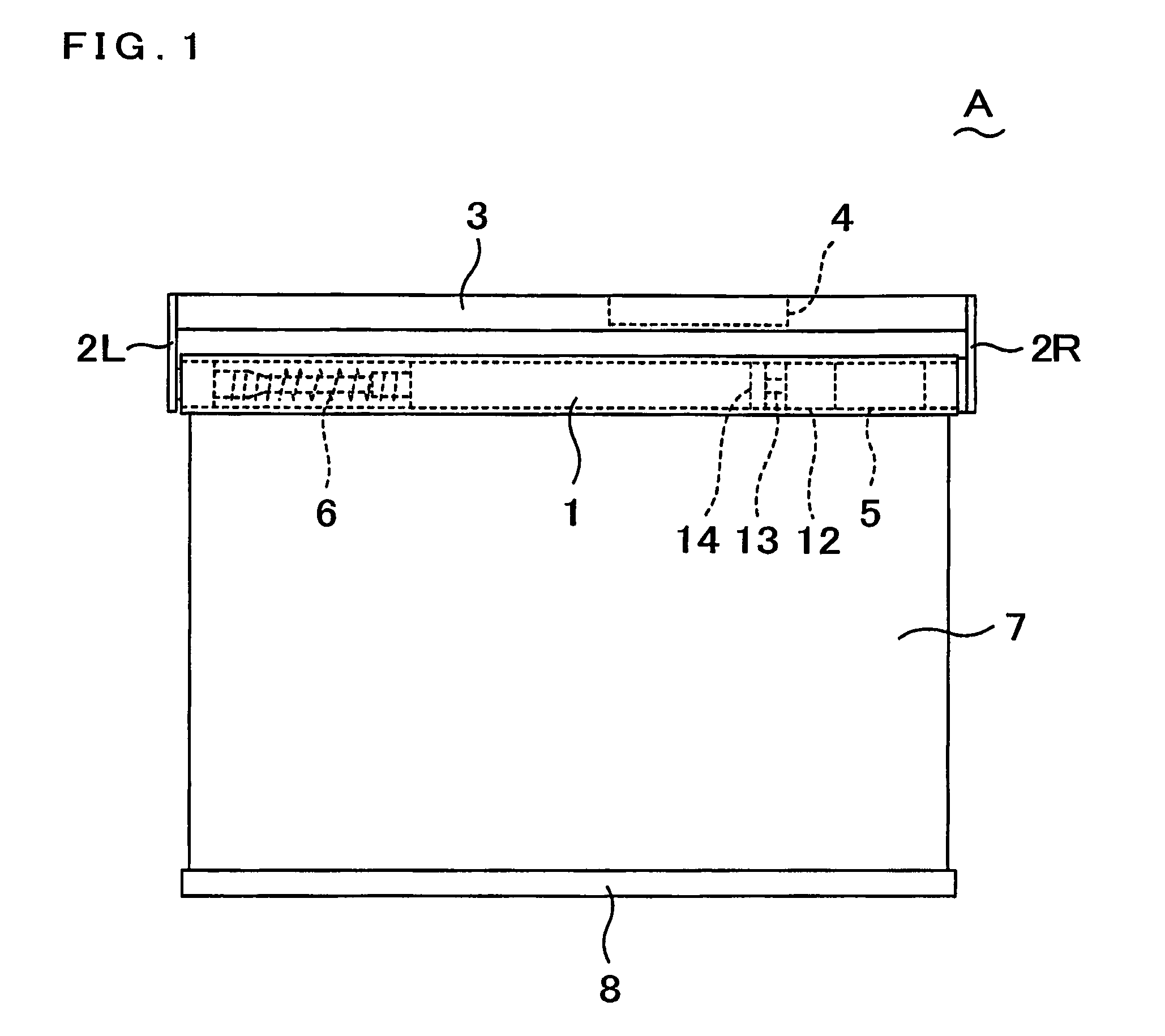
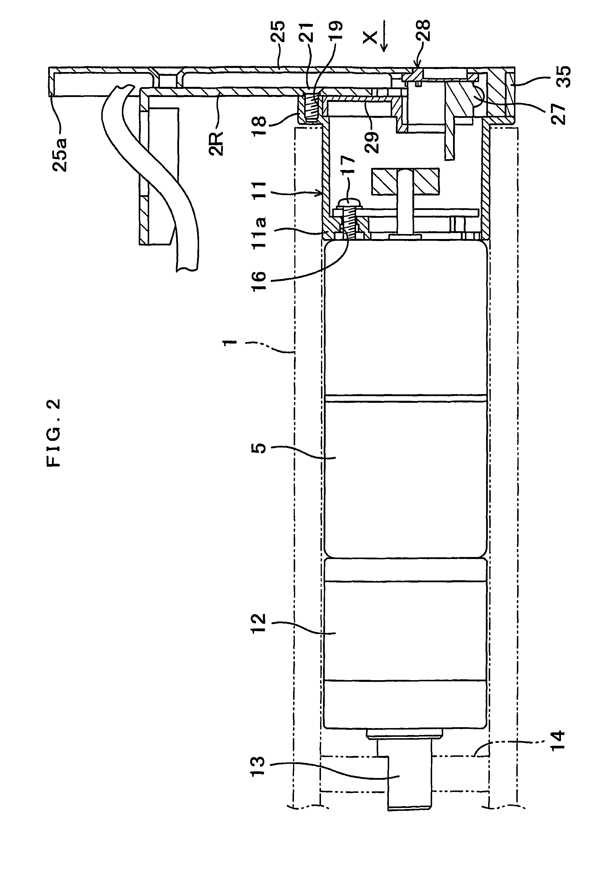
[0035]FIG. 1 shows an overall structure of an electric roll screen for blind having a remote-controlled light receiving structure according to an embodiment of the present invention. The electric roll screen A is provided with a take-up pipe 1 placed along an upper edge of a window of a building. The take-up pipe 1 is rotatably supported at both ends thereof by right and left side brackets 2R, 2L. Upper ends of the side brackets 2L, 2R are connected to a mounting frame 3 fixed to a ceiling or a side wall of a building, and a control panel 4 is mounted on an inner side of the mounting frame 3. While the side brackets 2L, 2R are illustrated to be exposed in FIG. 1, they are actually covered with bracket covers 25, respectively (See FIG. 2 showing the right side bracket 2R only).

[0036]A motor 5 for driving the t...


PUM


Abstract

A take-up pipe 1 is placed along an upper edge of a window of a building and is rotatably supported by side brackets 2R. An upper end of the screen having a weight bar attached to a lower end thereof, is fixed to the take-up pipe, so that the take-up pipe is rotated in forward and reverse directions by a motor 5 to wind up and down the screen. A light receiving unit 27 to receive a pulsed optical signal applied from a remote controller is mounted on the side bracket and is arranged so that it can be switched to two different orientations where the light receiving directions are symmetric with respect to a vertically downward direction and the phases are different from each other. By virtue of this, irrespective of the installation constraint of the electric roll screen, the remote-control of the electric roll screen can be effected.

Description

TECHNICAL FIELD[0001]The present invention relates to a remote-controlled light receiving structure of an electric roll screen for blind mounted on a window of a building.BACKGROUND ART[0002]In general, an electric roll screen for blind as is disclosed by JP Laid-open (Unexamined) patent publication No. Hei 10-46964, for example, is known as this type one which is structured so that a take-up pipe mounted along an upper edge of a window of a building is rotatably supported at both ends thereof by side brackets (or side plates), while an upper end of the screen as a window shade is fixed to the take-up pipe and a weight bar is attached to a lower end of the screen, so that the take-up pipe is rotated in forward and reverse directions by a motor to wind up and down the screen. In this type one, the motor is placed in the take-up pipe or at some other place outside the take-up pipe, for example, at either of the side brackets.[0003]The electric roll screen may be adapted to be remote-c...

Claims


Application Information

Patent Timeline
Patent Type & Authority Patents(United States)
IPC IPC(8): H04L17/02
CPCE06B9/72E06B9/50
Inventor INOUE, TAKUYAFUNAISHI, MUTSUMASA
Owner SHINSEI SEIKI
Why Eureka
Try Eureka