System and method for dynamic allocation of virtual machines in a virtual server environment

a virtual server and dynamic allocation technology, applied in the field of virtual server environments, can solve the problems of increasing complexity, increasing errors and inefficiencies, and manual management techniques that have proven to produce high errors and inefficiencies, and achieve the effect of high/faster performance capabilities

Active Publication Date: 2012-09-04
NETWORK APPLIANCE INC
View PDF7 Cites 60 Cited by
  • Summary
  • Abstract
  • Description
  • Claims
  • Application Information

AI Technical Summary

Benefits of technology

[0015]As such, as described herein, the rate at which a server (executing a processing thread and hypervisor module) produces VMs on the server will largely be a function of the “real-world” performance capabilities of the server, whereby servers having relatively higher / faster performance capabilities (e.g., newer servers, or servers under less load, or servers with more resources) will naturally have more VMs produced on them by its corresponding processing thread than servers having relatively lower / slower performance capabilities (e.g., servers under heavy load, running a large number of legacy VMs, or servers with fewer resources). This dynamic allocation of VMs based on such a “natural selection” technique may provide an appropriately balanced allocation of VMs across a plurality of servers based on the actual “real-world” performance capabilities of each server.

Problems solved by technology

As a result, these virtual server environments are becoming increasingly large and complex.
This increasing complexity is compounded by the heterogeneity of the different server types, different server manufacturers, different server configurations, and different storage requirements.
Manual management techniques have proven to produce high errors and inefficiencies.
For example, changes to the virtual server environment, which may happen frequently often due to rapid hardware and software life cycles, take a long time to complete using manual methods, and manual methods have proven to be error-prone.
The complexity of virtual server environments is further complicated by the increasing adoption of networked storage within virtual server environments (as disclosed in commonly-assigned U.S. patent application Ser. No. 12 / 283,163 filed on Sep. 9, 2008, the contents of which are incorporated herein in its entirety).
The difference in performance of different VM applications executing on different physical servers may be due to a variety of reasons that may be difficult to determine.
In many virtual server environments, however, there may be a reduction in application performance because too many VMs may be allocated to a lower performing server, while too few VMs may be allocated to another more capable server.
As a result, the overall resources of the virtual server environment (spread across the multiple physical servers) are not fully utilized in an efficient manner.
Given that the application performance of a server may be a function of many hardware or software variables, the complexity involved in modeling performance of a server may often produce inaccurate performance predictions.
As such, typically, once the VMs are allocated to servers and deployed for use by clients, static techniques result in an unbalanced deployment where too many VMs are allocated to a slower performing server and too few VMs are allocated to a faster performing server and often requires VMs to later be migrated among the servers.
The complexity involved in modeling performance of a physical server is also increased when application-access requirements to data on a storage system and storage system performance is also taken into account.
Static techniques that allocate predetermined numbers of VMs to particular servers, even those that model server performance and storage system performance, may still typically produce unbalanced allocation of VMs and require later migration of the VMs among the servers.

Method used


Image

  • System and method for dynamic allocation of virtual machines in a virtual server environment
  • System and method for dynamic allocation of virtual machines in a virtual server environment
  • System and method for dynamic allocation of virtual machines in a virtual server environment

Examples


Embodiment Construction

[0030]In the following description, numerous details are set forth for purpose of explanation. However, one of ordinary skill in the art will realize that the embodiments described herein may be practiced without the use of these specific details. In other instances, well-known structures and devices are shown in block diagram form in order to not obscure the description with unnecessary detail.

[0031]The description that follows is divided into three sections. Section I describes a virtual server environment in which some embodiments operate. Section II describes an apparatus for dynamic VM allocation in virtual server environments. Section III describes methods for dynamic VM allocation in virtual server environments.

I. Virtual Server Environment

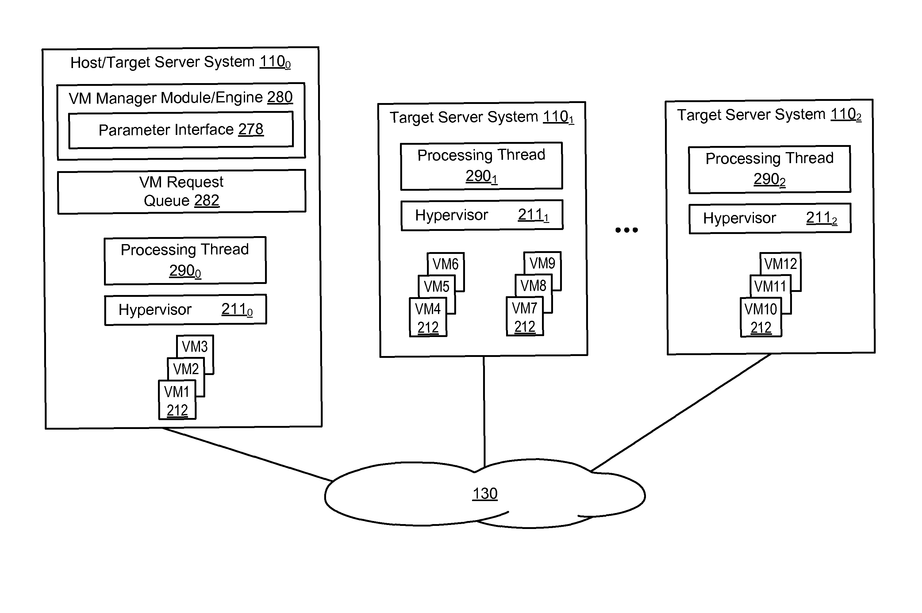
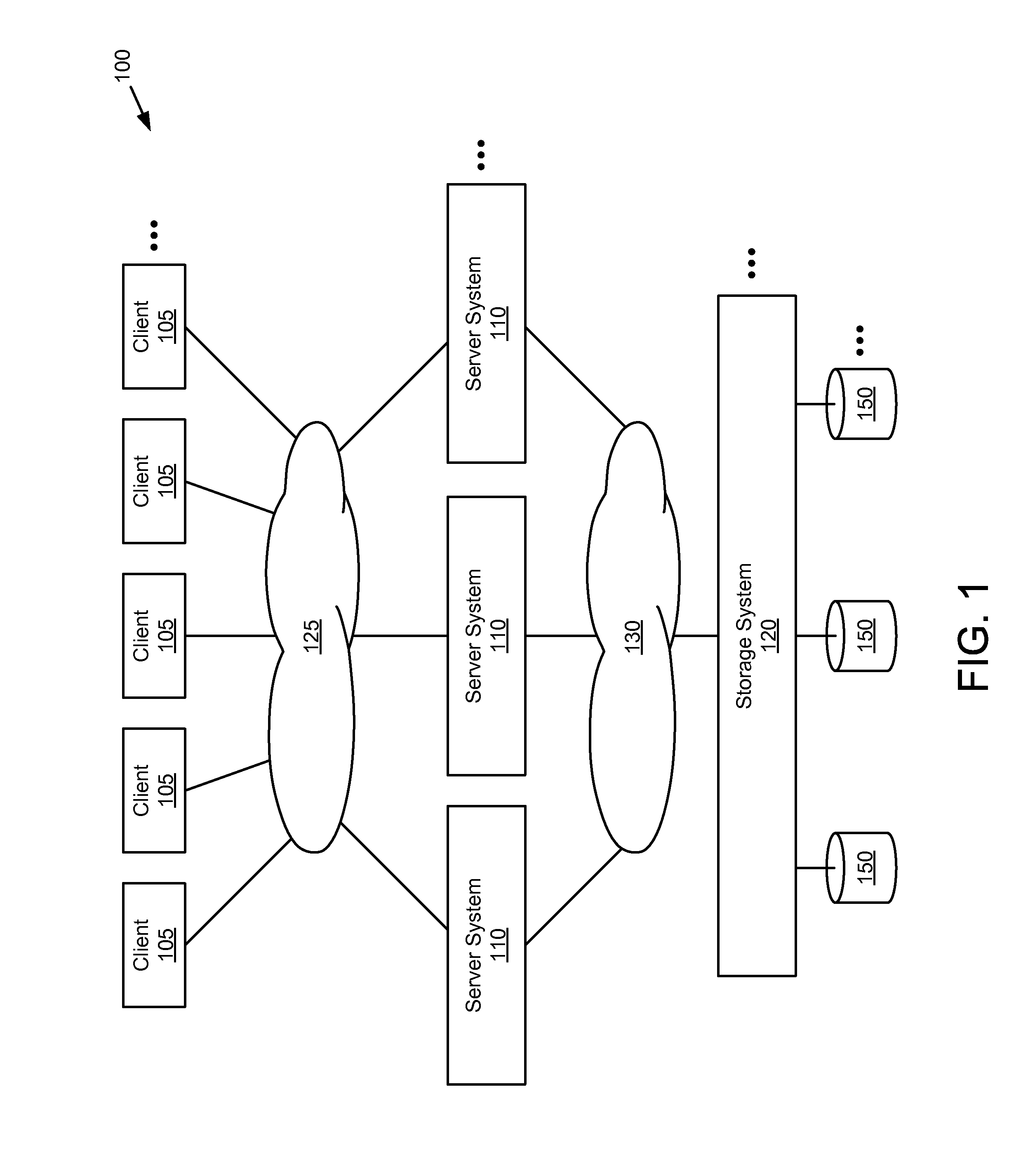
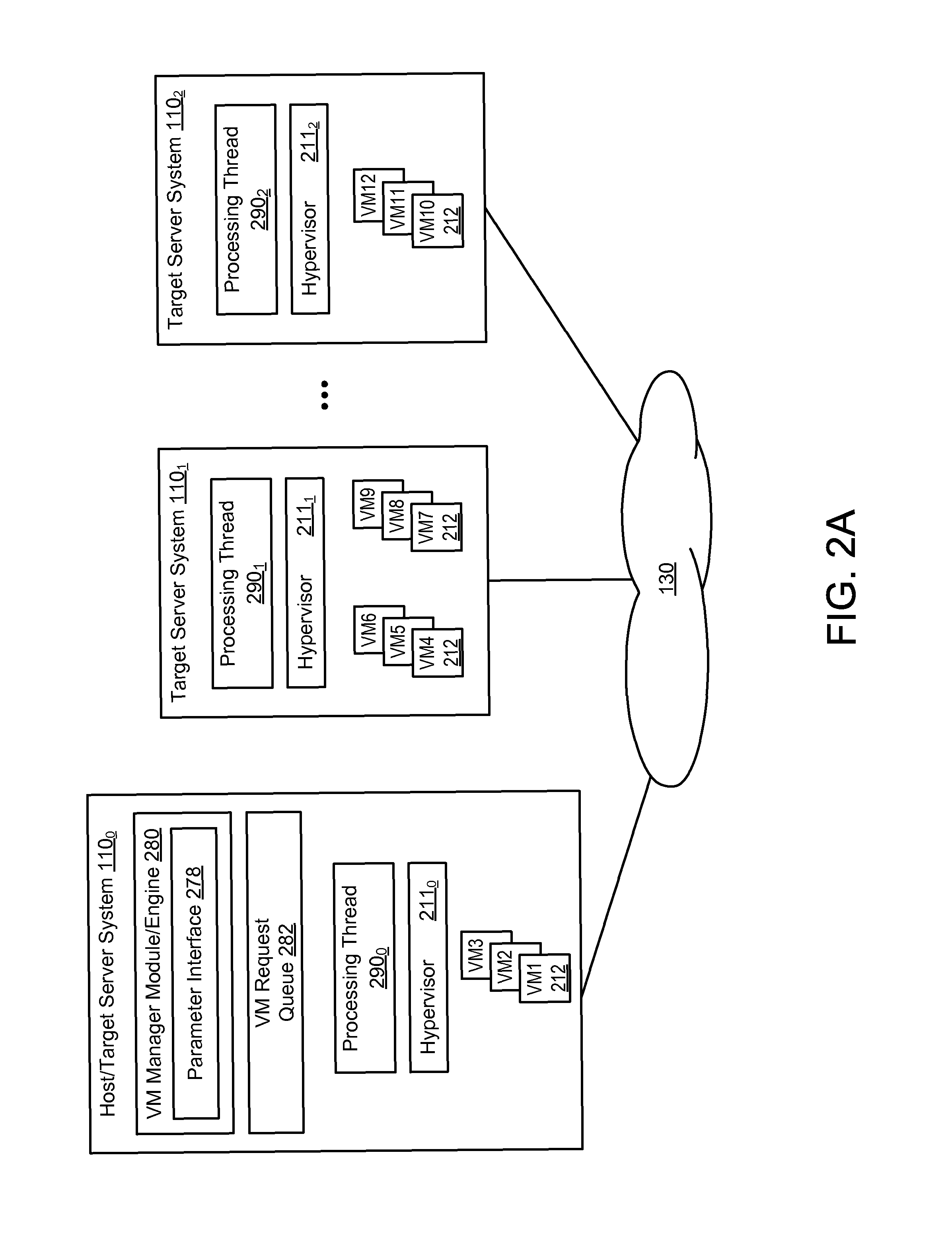
[0032]FIG. 1 is a block diagram of an exemplary virtual server environment 100 in which some embodiments operate. The environment 100 comprises a set of two or more server systems 110 connected to one or more client systems 105 via a networ...


PUM


Abstract

A system and method for dynamically producing virtual machines (VMs) across a plurality of servers in the virtual server environment is provided. A single VM request queue is produced comprising VM requests for producing the plurality of VMs. A processing thread is produced and assigned for each server and retrieves VM requests from the VM request queue and produces VMs only on the assigned server according to the retrieved VM requests. Each processing thread may be configured for retrieving VM requests and producing VMs without any programmed delays, whereby the rate at which a processing thread produces VMs on its assigned server is a function of the performance capabilities of the assigned server. This dynamic allocation of VMs based on such a “natural selection” technique may provide an appropriately balanced allocation of VMs based on the performance capabilities of each server in the virtual server environment.

Description

FIELD OF THE INVENTION[0001]The present invention relates to virtual server environments and, more specifically, to dynamic allocation of virtual machines in a virtual server environment.BACKGROUND OF THE INVENTION[0002]A virtual server environment may typically include multiple physical servers accessing a storage system having multiple storage devices for storing client data. Each server may include multiple virtual machines (VMs) that reside and execute on the server. Each VM (sometimes referred to as a virtual server or virtual desktop) may comprise a separate encapsulation or instance of a separate operating system and one or more applications that execute on the server. As such, each VM on a server may have its own operating system and set of applications and function as a self-contained package on the server and multiple operating systems may execute simultaneously on the server.[0003]Each VM on a server may be configured to share the hardware resources of the server. Each se...

Claims


Application Information

Patent Timeline
Patent Type & Authority Patents(United States)
IPC IPC(8): G06F9/455
CPCG06F9/45558G06F2009/4557
Inventor FORGETTE, ERIC P.
Owner NETWORK APPLIANCE INC
Why Eureka
Try Eureka