System for heating an airstream by recirculating waste heat of a turbomachine

a technology of waste heat and turbomachine, which is applied in the direction of machines/engines, liquid fuel engines, transportation and packaging, etc., can solve the problems of increasing the pressure drop across the inlet system, affecting the performance of the combustion turbine, and harming the combustion turbin

Inactive Publication Date: 2012-09-11
BHA ALTAIR
View PDF9 Cites 95 Cited by
  • Summary
  • Abstract
  • Description
  • Claims
  • Application Information

AI Technical Summary

Problems solved by technology

These environments allow ice to form (hereinafter “icing”) within the inlet system and on components down stream of the inlet system; which may be harmful to the combustion turbine.
Icing can also increase the pressure drop across inlet system; negatively affecting the performance of the combustion turbine.
During the operation of the combustion turbine, a tremendous amount of heat, which is not converted to useful work, is generated.
This waste heat can negatively impact various components.

Method used


Image

  • System for heating an airstream by recirculating waste heat of a turbomachine
  • System for heating an airstream by recirculating waste heat of a turbomachine
  • System for heating an airstream by recirculating waste heat of a turbomachine

Examples


first embodiment

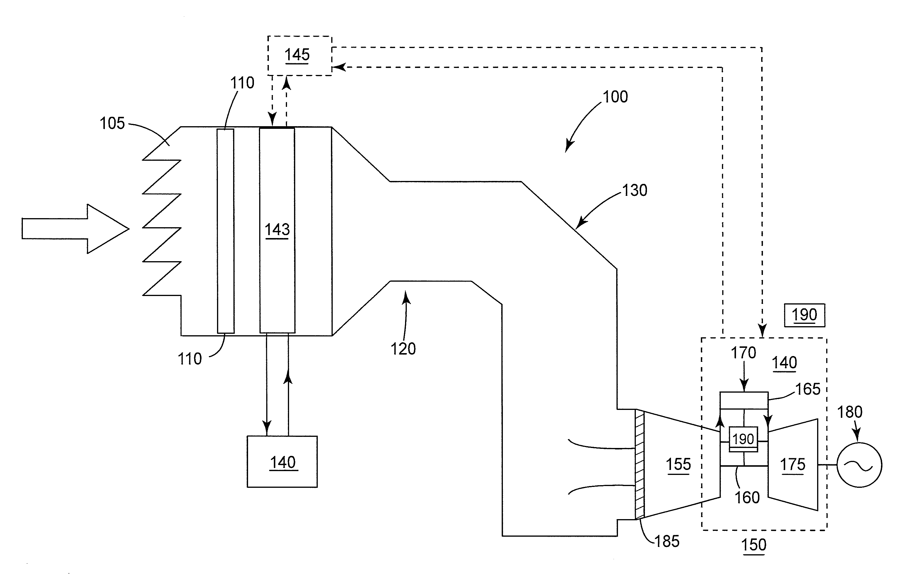
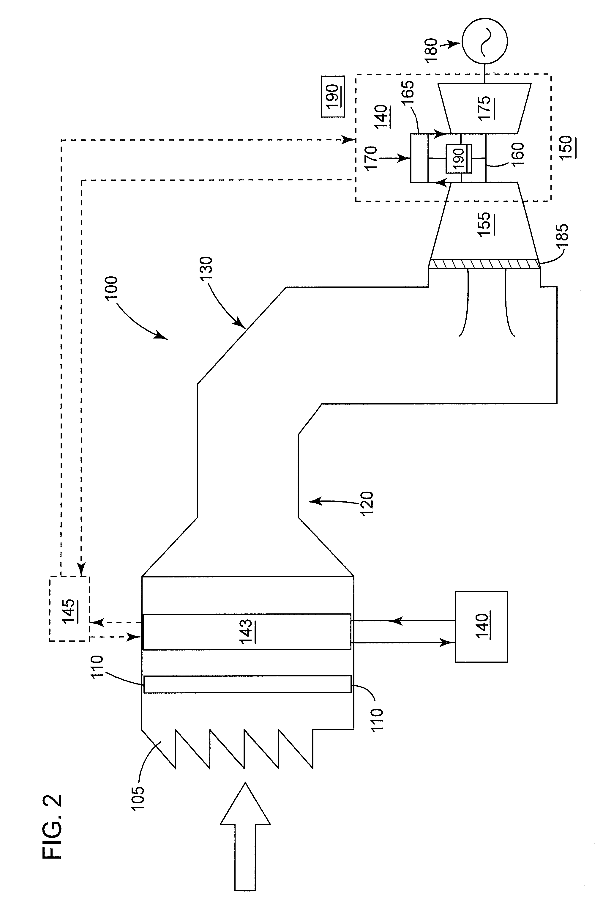
[0027]FIG. 2 is a schematic illustrating a system for increasing the temperature of an airstream entering a combustion turbine 150, in accordance with embodiments of the present invention. FIG. 2 illustrates the inlet system 100, of FIG. 1, integrated with a waste heat source 140 and an air preheating system 143, in accordance with the present invention. The operational goal of the waste heat source 140 is to increase the temperature of the airstream flowing within the inlet system 100, when ambient conditions allow for icing to occur. This may reduce the need to operate the IBH system 125, possibly increasing the efficiency and the output of the combustion turbine 150.

[0028]The waste heat derives from the combustion turbine 150, and is recovered with the aim of increasing the airstream temperature, when needed. The waste heat source 140 removes heat from the associated components of the combustion turbine 150. Embodiments of the present invention may use multiple approaches to incr...

second embodiment

[0037]Referring now to FIG. 4, which is a schematic illustrating a waste heat source 140 of FIG. 1, in accordance with the present invention. FIG. 4 illustrates a lube oil system 400, which serves to lubricate, inter alia, a bearing 430 of the combustion turbine 150. A pump 420 serves to circulate the lube oil throughout the lube oil system 400. The lube oil flows from the tank through the pump 420 and then to the bearing 430. The lube oil removes heat from the bearing 430 and associated structure, thereby increasing the temperature of the lube oil (herein after “hearted oil”). The heated oil may then flow directly, or indirectly via the external heat exchanger 145, to the air preheating system 143. Here, the heated oil may increase the temperature of the airstream, as the temperature of the heated oil is decreased (hereinafter “lube oil”). Next, the lube oil may flow through a heat exchanger 440; which may function to adjust the lube oil temperature to a desirable rang prior to ret...


PUM


Abstract

An embodiment of the present invention takes the form of an application and process that incorporates a waste heat source to increase the temperature of the airstream entering an inlet section of a combustion turbine. An embodiment of the present invention may perform an anti-icing operation that reduces the need to operate the IBH system.

Description

[0001]This application is a continuation of application Ser. No. 12 / 757,442, filed on Apr. 9, 2010, now abandoned.BACKGROUND OF THE INVENTION[0002]The present invention relates to an anti-icing system of a combustion turbine; and more particularly to an anti-icing system that uses a waste heat source from the combustion turbine.[0003]Some combustion turbines operate in cold and humid environments. These environments allow ice to form (hereinafter “icing”) within the inlet system and on components down stream of the inlet system; which may be harmful to the combustion turbine. Icing can also increase the pressure drop across inlet system; negatively affecting the performance of the combustion turbine.[0004]Anti-icing systems are used to prevent or remove icing. These systems may be a function of an inlet bleed heat system (IBH), which re-circulates hot compressor discharge air to the inlet system, raising the temperature of the inlet airstream. Furthermore, anti-icing systems typical...

Claims


Application Information

Patent Timeline
Patent Type & Authority Patents(United States)
IPC IPC(8): F02C7/047F02C7/08
CPCF02C1/08F02C3/34F02C6/08F02C7/047F02C7/08
Inventor CHILLAR, RAHUL JAIKARANUPADHYAY, SIDDHARTH GIRISHKUMAR
Owner BHA ALTAIR
Why Eureka
Try Eureka