Variable stroke engine

a variable stroke, internal combustion engine technology, applied in the direction of engines, machines/engines, mechanical equipment, etc., can solve the problems of unfavorable use of servomotors which are compact and consume little power, large mounting space, and large engine size, so as to reduce the weight of the drive shaft, enhance the reliability of the actuator, and reduce the size of the actuator.

Active Publication Date: 2012-09-11
HONDA MOTOR CO LTD
View PDF14 Cites 7 Cited by
  • Summary
  • Abstract
  • Description
  • Claims
  • Application Information

AI Technical Summary

Benefits of technology

[0015]A second object of the present invention is to provide an improved variable stroke engine that can simplify the power actuator means for angularly actuating an control shaft.
[0016]A third object of the present invention is to provide a variable stroke engine that can apply a biasing torque to the control shaft at an appropriate level for driving the control shaft in either direction without increasing the size of the engine in the direction of the control shaft, and that can offer a high level of freedom in designing the biasing torque.
[0017]A fourth object of the present invention is to provide a variable stroke engine that can apply a biasing torque to the control shaft at an appropriate level for driving the control shaft in either direction without increasing the weight of the engine, and that can offer a high level of freedom in designing the biasing torque.
[0021]If the engine further comprises a spring member that biases the control member in one of the two directions, the shortfall in the actuating force provided by the inertia force of the piston undergoing a reciprocating movement can be filled by the spring force, and by suitably adjusting the supplementary input, the displacing speed of the connecting point may be accelerated when moving from the high compression ratio side to the low compression ratio side, and the compression ratio can be quickly changed so that engine knocking can be avoided when rapidly accelerating the engine. Such a spring member may consist of a torsion coil spring, but may also consist of a compression coil spring interposed between an arm of the control shaft and an engine main body.
[0022]If the spring member is at least partly received in a housing wall of the actuator or is otherwise at least partly received in a part of the actuator, the size of the actuator fitted with the spring biasing means can be minimized, and the spring biasing means is prevented from interfering with the other component parts so that the reliability of the actuator can be enhanced. In particular, if the spring member is received at least partly received in drive shaft of the actuator, the internal space of the drive shaft is effectively utilized, and the size of the actuator can be both reduced.
[0023]If the spring member extends at least partly along a bearing journal of the drive shaft, the weight of the drive shaft can be reduced, and the size of the actuator can be even further reduced.

Problems solved by technology

Therefore, this prior art prevents the use of a servomotor which is compact and consumes little power.
In such a variable stroke engine, because the spring biasing means associated with the actuator is provided separately from the actuator, the actuator attached with the spring biasing means requires a large mounting space.
This, combined with the need to avoid the interference of the spring biasing means with the surrounding component parts, caused the size of the engine to be come undesirably large.
2004-150353 and Japanese patent laid open (kokai) publication No. 2003-322036, because of the need for a hydraulic circuit including a hydraulic pump, a hydraulic actuator and a control valve, the increased complexity of the system complicates the manufacturing process and causes an increase in the size and weight of the system.
In particular, when a relatively large torque is required, the wire diameter of the spiral spring has to be increased, and the diameter of the spiral spring may become so great that there may be some difficulty in installing the spiral spring in the engine.
If the spiral spring is closely wound so as to reduce the overall diameter of the spiral spring, the friction between adjacent turns of the coil wire causes a hysteresis that prevents the generation of an appropriate torque.
Even when a torsion coil spring is used in a similar arrangement, the tilting of the coil spring may cause a hysteresis.
Again, when the diameter of the coil wire is increased to ensure a required torque to be produced and the number of turns is increased to ensure a required range of rotational angle, the size of the coil spring in the axial direction of the control shaft inevitably increases, and this causes a problem when installing the coil spring in the engine.

Method used


Image

  • Variable stroke engine
  • Variable stroke engine
  • Variable stroke engine

Examples


second embodiment

[0050]As shown in FIGS. 8 to 11, the variable compression ratio engine E given as the present invention consists of an automotive engine which is laterally placed (with a crankshaft 30 thereof oriented laterally with respect to the traveling direction of the motor vehicle) in the engine room of the motor vehicle not shown in the drawings. The engine E is mounted in the engine room in such a manner that the engine is somewhat tilted rearward or the cylinder axial line L-L is somewhat tilted rearward with respect to a vehicle line V-V (See FIG. 9).

[0051]This variable compression ratio engine E consists of an in-line, four-cylinder, four-stroke OHC engine, and an engine main body 1 thereof comprises a cylinder block 2 formed with four cylinders 5 arranged laterally one next another, a cylinder head 3 integrally attached to a deck surface of the cylinder block 2 via a gasket 6, an upper block 40 (upper crankcase) integrally formed in a lower part of the cylinder block 2, and a lower blo...

third embodiment

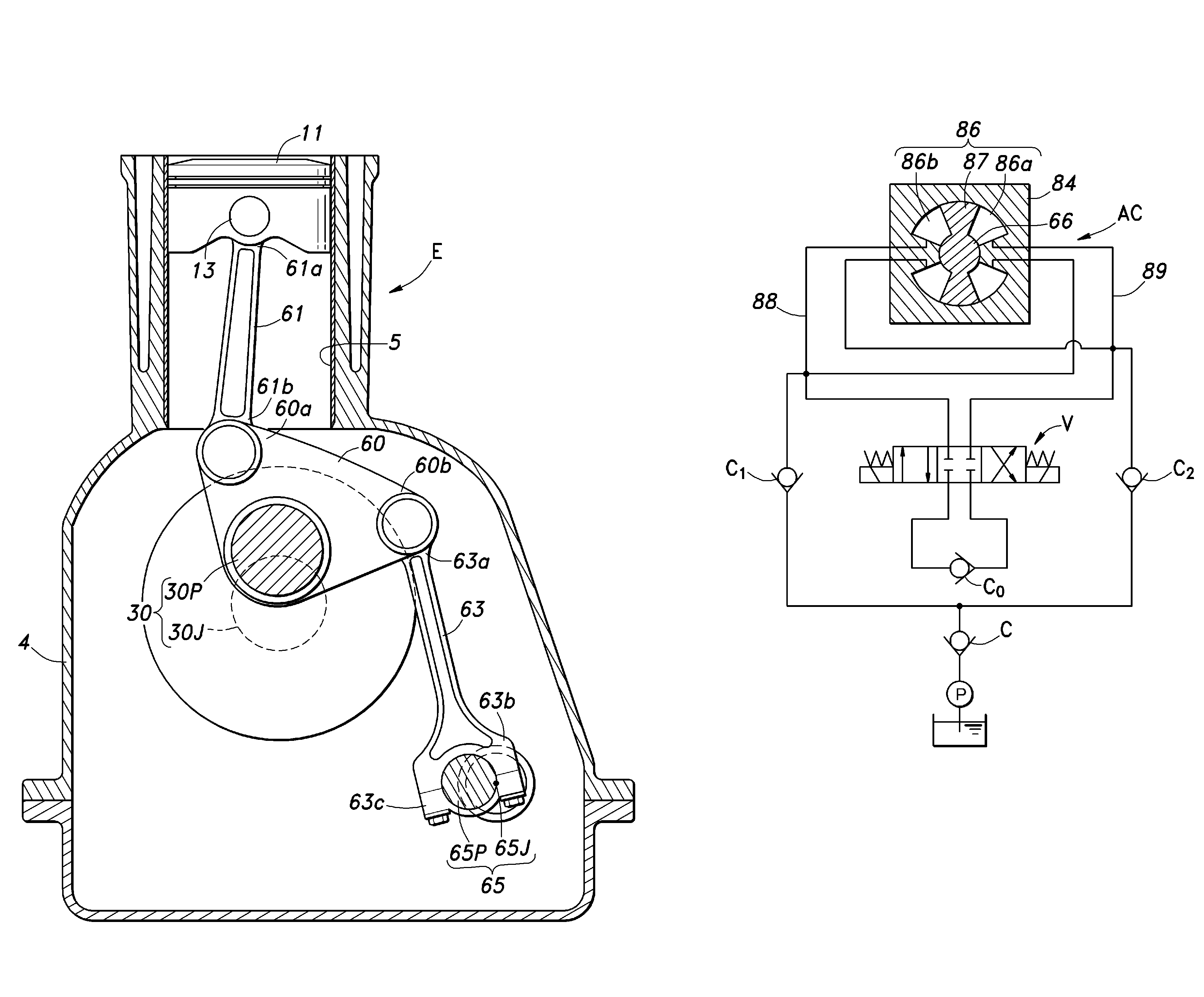
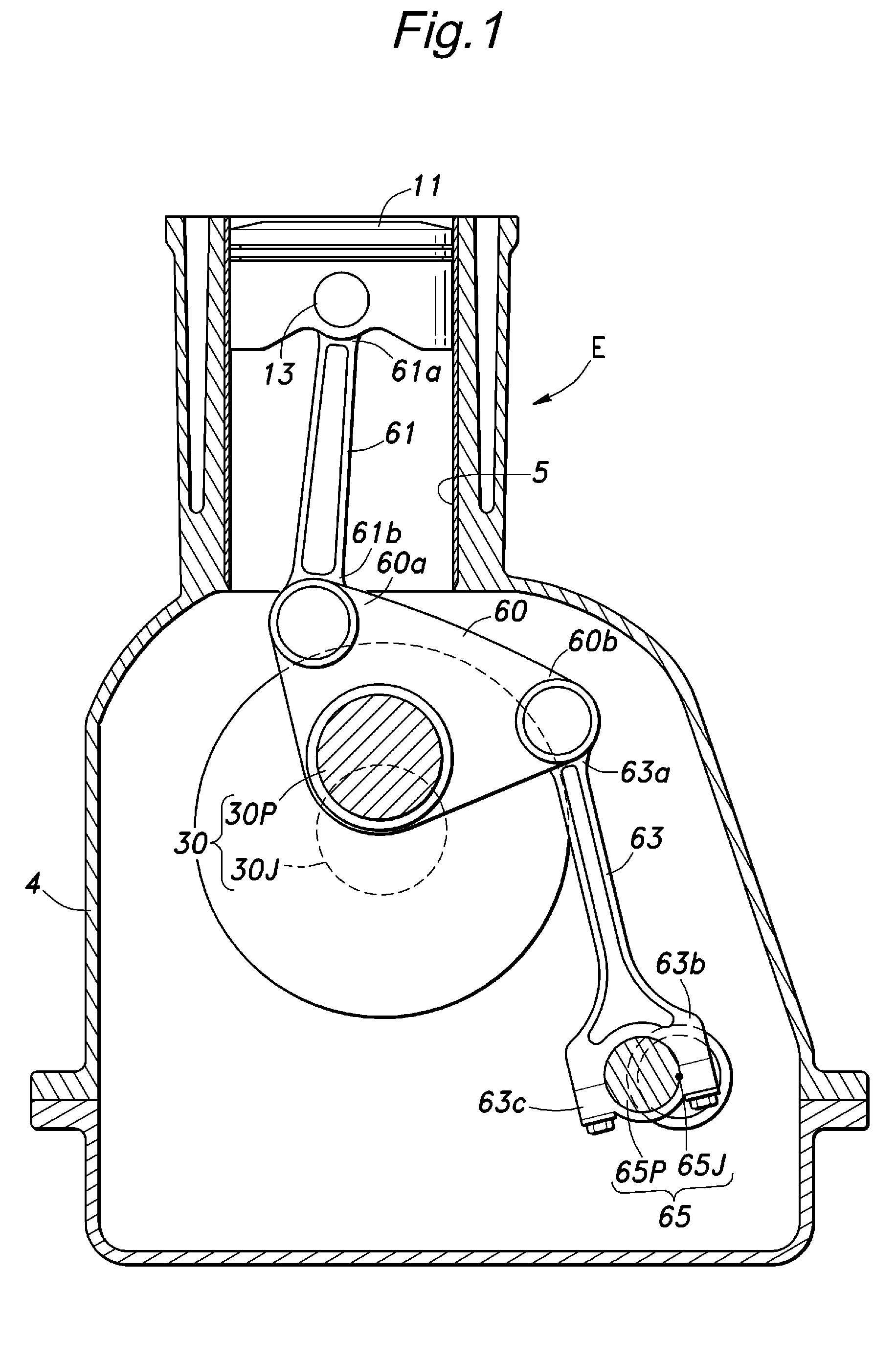
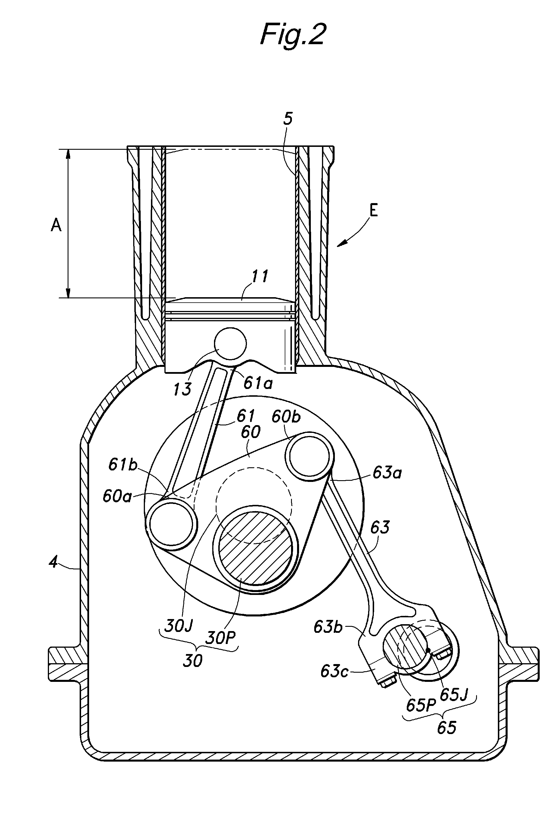
[0075]The engine E given as the present invention and illustrated in FIG. 17 consists of an in-line four-cylinder engine, and a vertical sectional view of one of the cylinders is shown in FIG. 17. A piston 11 that is slidably received in the cylinder 5 of the engine E is connected to a crankshaft 30 via an upper link 61 and a lower link 60.

[0076]The crankshaft 30 is essentially no different from that of a conventional fixed compression ratio engine, and comprises a crank journal 30J (rotational center of the crankshaft) supported by a crankcase (engine main body) 4 and a crankpin 30P radially offset from the crank journal 30J. An intermediate point of the lower link 60 is supported by the crankpin 30P so as to be able to tilt like a seesaw. An end 60a of the lower link 60 is connected to a big end 61b of the upper link 61, and a small end 61a of the upper link 61 is connected to a piston pin 13.

[0077]The other end 60b of the lower link 60 is connected to a small end 63a of a control...

fourth embodiment

[0107]The engine E given as the present invention and illustrated in FIG. 21 consists of an in-line four-cylinder engine, and a vertical sectional view of one of the cylinders is shown in FIG. 21. A crankcase 4 is formed by joining a cylinder block 4a and a bearing block 4b with each other, and an oil pan 10 is attached to the bottom end of the crankcase 4 to receive oil that is plashed in the crankcase 4. A piston 11 is slidably received in the cylinder 5 formed in an upper part of the cylinder block 4a, and is connected to a crankshaft 30 via an upper link 61 and a lower link 60.

[0108]The crankshaft 30 is essentially no different from that of a conventional fixed compression ratio engine, and comprises a crank journal 30J (rotational center of the crankshaft) supported by a crankcase (engine main body) 4 and a crankpin 30P radially offset from the crank journal 30J. An intermediate point of the lower link 60 is supported by the crankpin 30P so as to be able to tilt like a seesaw. ...


PUM


Abstract

In a variable stroke engine comprising a plurality of links (60, 61) connecting a piston (11) with a crankshaft (30), a control member (65) disposed on an engine main body so as to be moveable in two directions over a prescribed range relative to the engine main body, a control link (63) connecting one of the plurality of links with the control member and an actuator (AC) for displacing the control member, the actuator comprises a ratchet mechanism that utilizes a force transmitted from the piston to the control member as an actuating force for the control member. By providing a spring member (73, SP, 121) that applies a biasing force to the control member, an appropriate actuating force can be applied to the control member in either direction.

Description

RELATED APPLICATIONS[0001]This application is a 35 U.S.C. 371 national stage filing of International Application No. PCT / JP2007 / 000972, filed on Sep. 7, 2007, which claims priority to Japanese Patent Application No. 2006-250946 filed on Sep. 15, 2006, Japanese Patent Application No. 2006-250937 filed on Sep. 15, 2006, Japanese Patent Application No. 2006-259576 filed on Sep. 25, 2006, and Japanese Patent Application No. 2006-303125 filed on Nov. 8, 2006 in Japan. The contents of the aforementioned applications are hereby incorporated by reference.TECHNICAL FIELD[0002]The present invention relates to a variable stroke internal combustion engine, and in particular to a variable stroke engine that can simplify the power actuator for changing the stroke property.PRIOR ART[0003]Known is a variable stroke engine that comprises a plurality of links connecting a piston with a crankshaft, and a control link connecting one of the plurality of links with an control shaft supported by an engine...

Claims


Application Information

Patent Timeline
Patent Type & Authority Patents(United States)
IPC IPC(8): F02B75/04F02D15/02
CPCF02B75/048F02D15/02
Inventor YOSHIKAWA, TAICHITANAKA, SHIGEKAZUFUJIMOTO, JIRONAKANISHI, KEITAROFUJII, NORIAKIMAEZURU, AKINORI
Owner HONDA MOTOR CO LTD
Why Eureka
Try Eureka