Motor vehicle wheel structure

a technology for motor vehicles and wheels, applied in the direction of disc wheels, vehicle components, transportation and packaging, etc., can solve the problem of having a relatively high cost and achieve the effect of improving characteristics and even superior stiffness

Inactive Publication Date: 2012-09-11
CENT RICERCHE FIAT SCPA
View PDF11 Cites 3 Cited by
  • Summary
  • Abstract
  • Description
  • Claims
  • Application Information

AI Technical Summary

Benefits of technology

[0004]The object of the present invention is to provide a wheel structure having improved characteristics from the standpoint of static and dynamic stiffness, which will, for example, enable production of a wheel made of steel plate with characteristics of stiffness similar to those of a conventional wheel made of light alloy, or else again that will enable production of a wheel made of light alloy with characteristics of stiffness even superior to those of wheels made of light alloy of a conventional type.
[0005]In general, the object of the invention is to provide a wheel characterized by a high static and dynamic stiffness and such as to reduce to the minimum the noise due to the deformations and vibrations resulting from rolling on the ground, as the motor vehicle is travelling.
[0006]A further purpose of the invention is to achieve the aforesaid target with a relatively simple and inexpensive structure.
[0014]Tests conducted by the present applicant have shown that the wheel structure thus made enables a considerable increase in the static and dynamic stiffness of the wheel to be obtained and a consequent considerable reduction of the noise in the passenger compartment of the motor vehicle when the latter is travelling.

Problems solved by technology

From this standpoint, wheels made of light alloy in general enable an excellent result to be obtained since they are considerably stiffer than wheels made of steel plate, but present the drawback of having a relatively high cost.

Method used


Image

  • Motor vehicle wheel structure
  • Motor vehicle wheel structure
  • Motor vehicle wheel structure

Examples


Embodiment Construction

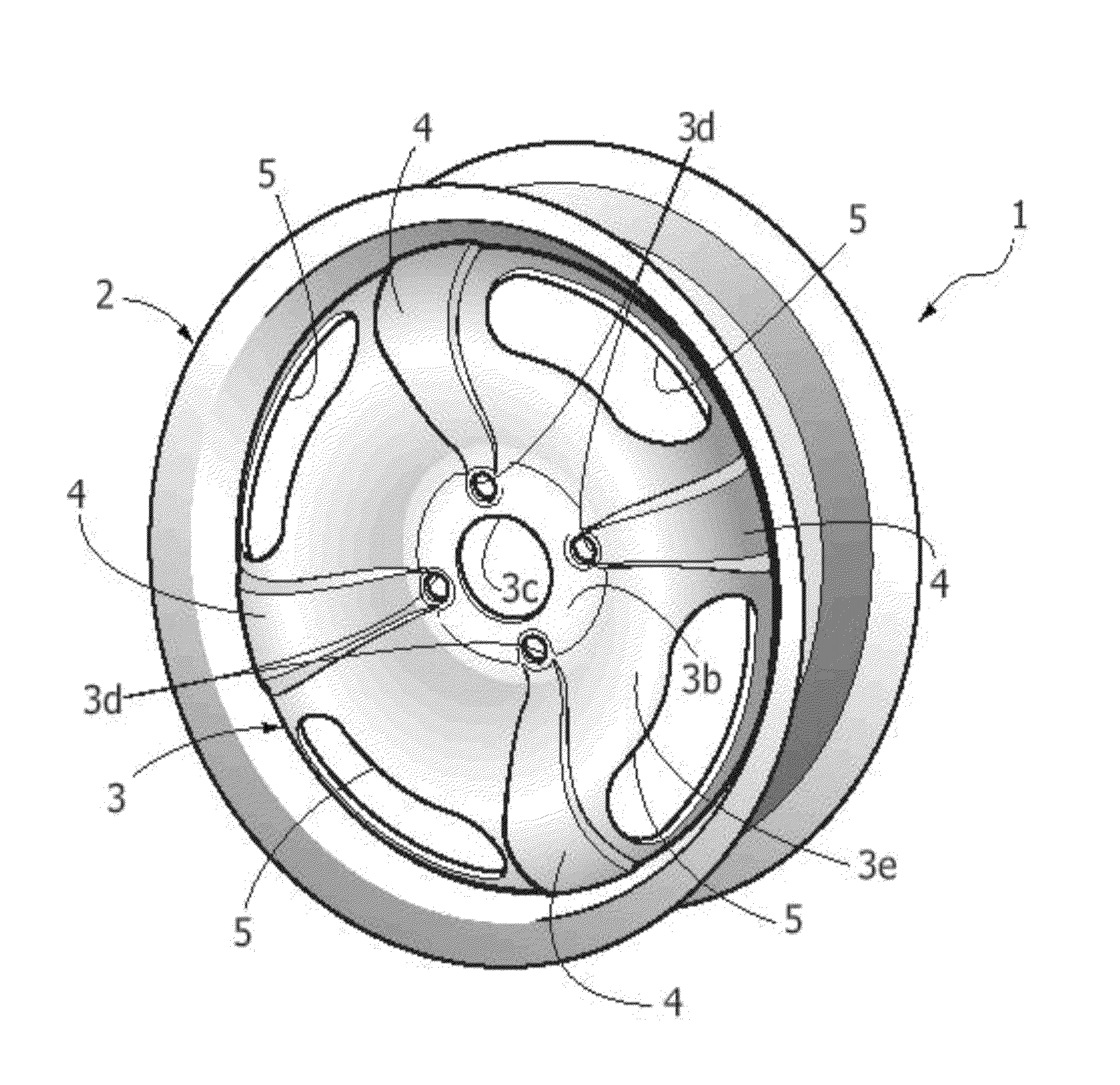
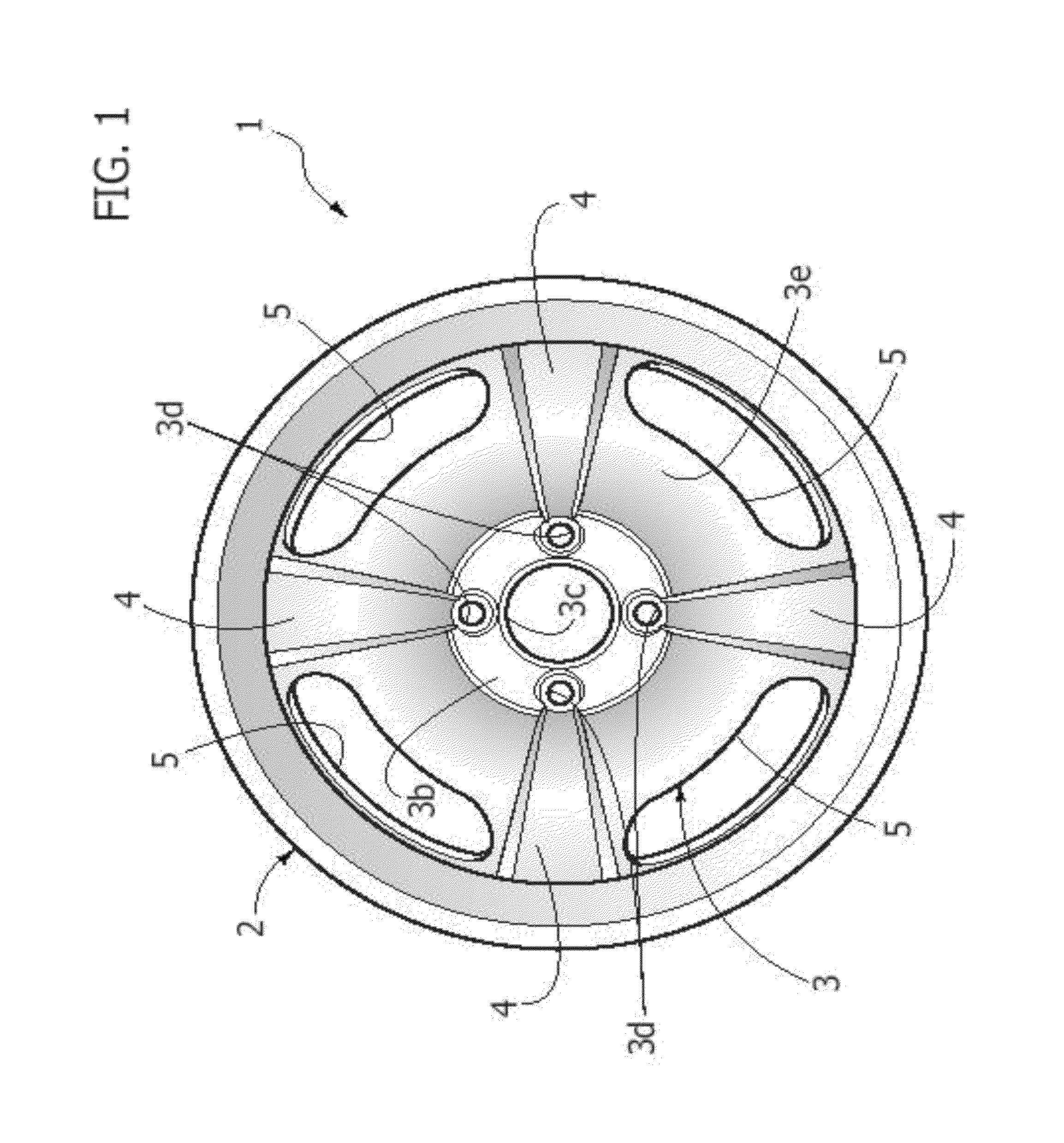
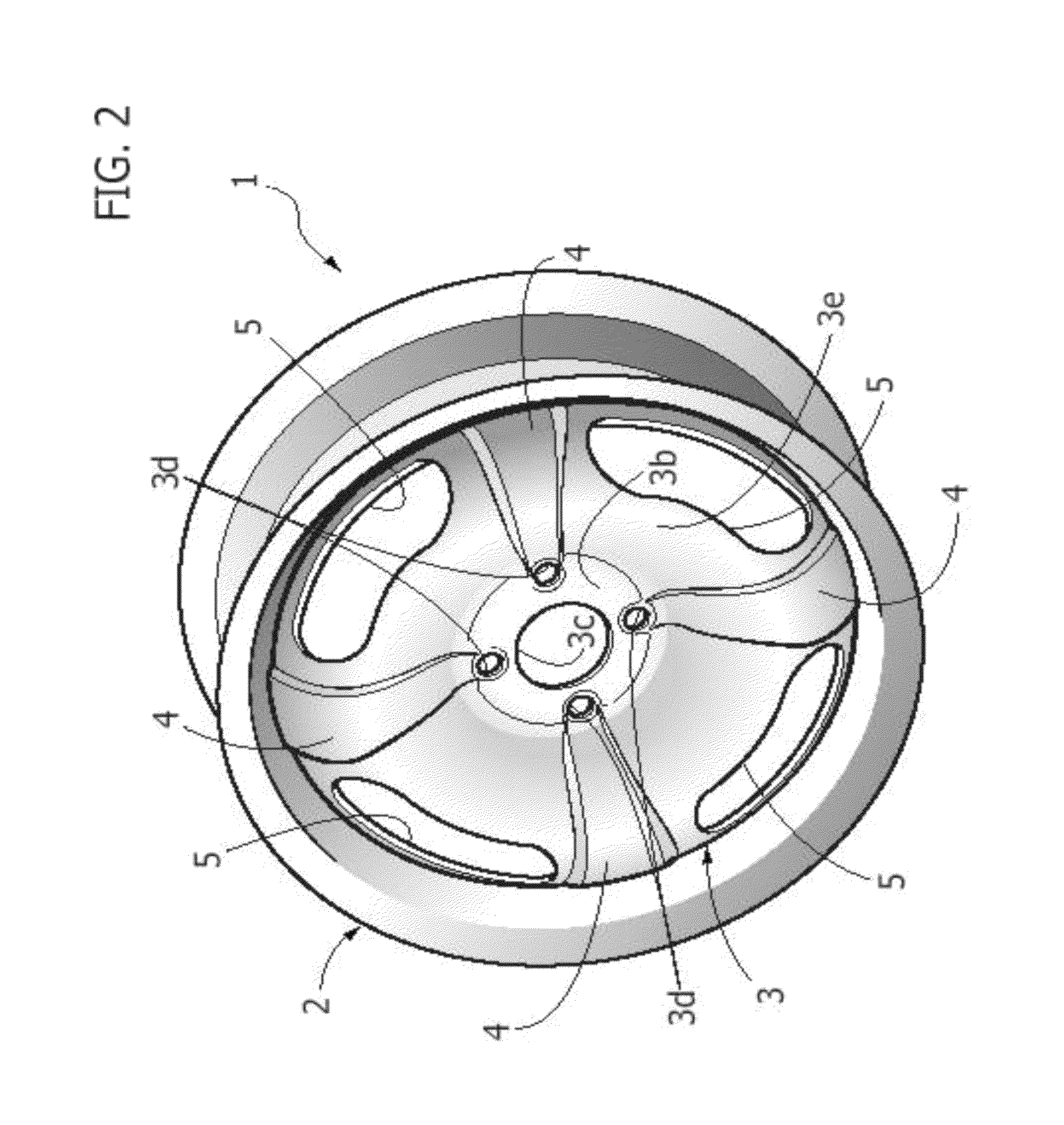
[0022]With reference to the drawings, number 1 designates as a whole a wheel structure comprising a wheel rim 2 made of stamped steel plate and a wheel disk 3.

[0023]The disk 3 has an outer circumferential border 3a (FIG. 3) bent so as to define an intermediate cylindrical wall 2a of the rim 2.

[0024]The wheel disk 3 moreover presents a central portion 3b having a central hub 3c for mounting on the corresponding part of a wheel support, and a plurality of holes 3d for engagement of bolts for fixing the wheel to the wheel support. The central portion 3b of the disk 3 is radiused with the outer circumferential border 3a by means of an intermediate annular portion 3e, which has, in cross section, an arched profile projecting outwards so as to have its apex substantially tangential to the outer end plane of the wheel rim 2.

[0025]According to the invention, the intermediate annular portion 3e of the disk made of steel plate has a plurality of embossed portions 4, projecting outwards, confi...


PUM


Abstract

A motor-vehicle wheel structure comprises a wheel rim and a wheel disk having a circumferential border bent and welded within the wheel rim, and a central portion bearing a circumferential series of holes for engagement of bolts for fixing the wheel to the wheel support. The central portion is radiused to the circumferential border of the disk by means of an intermediate annular portion having in cross section an arched configuration projecting outwards. The intermediate annular portion has a plurality of embossed portions projecting outwards, configured in such a way as to define a plurality of spokes set at the same angular distance apart from one another.

Description

BACKGROUND OF THE INVENTION[0001]The present invention relates to metal structures of motor-vehicle wheels, of the type comprising a wheel rim and a wheel disk having a circumferential border bent and welded within the rim, the disk moreover having a central portion with a circumferential series of holes for engagement of bolts for fixing the wheel to a wheel support, said central portion of the wheel disk being radiused with the aforesaid outer circumferential border by an intermediate annular portion of the wheel disk having in cross section an arched conformation, projecting outwards.[0002]The problem underlying the present invention is that of providing a wheel structure that will be able to reduce to the minimum the deformations and vibrations to which the wheel is subject as it rolls on the ground, with consequent reduction of the level of noise that is perceived inside the passenger compartment of a motor vehicle.[0003]Studies and tests conducted by the present applicant have...

Claims


Application Information

Patent Timeline
Patent Type & Authority Patents(United States)
IPC IPC(8): B60B3/10
CPCB60B3/002B60B3/044B60B3/10
Inventor TRENTIN, MARCELLOVIGE, DAVIDEPEYRON, BENEDETTABOREANAZ, GIOVANNIMONFRINO, GIOVANNI
Owner CENT RICERCHE FIAT SCPA
Why Eureka
Try Eureka