Shield connector

a shield connector and connector technology, applied in the direction of coupling device connection, coupling protective earth/shielding arrangement, electrical equipment, etc., can solve the problems of resilient contact piece caught, damaged or deformed, etc., to prevent the inclination restrict the position of the shell main body, and high contact pressure

Active Publication Date: 2012-09-11
SUMITOMO WIRING SYST LTD
View PDF13 Cites 23 Cited by
  • Summary
  • Abstract
  • Description
  • Claims
  • Application Information

AI Technical Summary

Benefits of technology

[0012]At least one elongated projection is provided on the inner side of the protection wall and projects in to restrict the position of the shell main body and to prevent inclination of the shell main body. Therefore, the resilient contact piece can be held stably in contact with the surface of the mounting member and a high contact pressure of the resilient contact piece with the surface of the shaft hole is ensured.
[0013]A taper preferably is formed at or near the rear end of the elongated projection, so that the shield shell can be assembled smoothly into the terminal mounting portion.
[0014]A stopper preferably is formed on the shell main body substantially in correspondence with the resilient contact piece to prevent an excessive deformation of the resilient contact piece.

Problems solved by technology

Thus, there is a possibility that the resilient contact piece is caught and damaged or deformed when the connector is carried around or assembled.

Method used


Image

  • Shield connector
  • Shield connector
  • Shield connector

Examples


Embodiment Construction

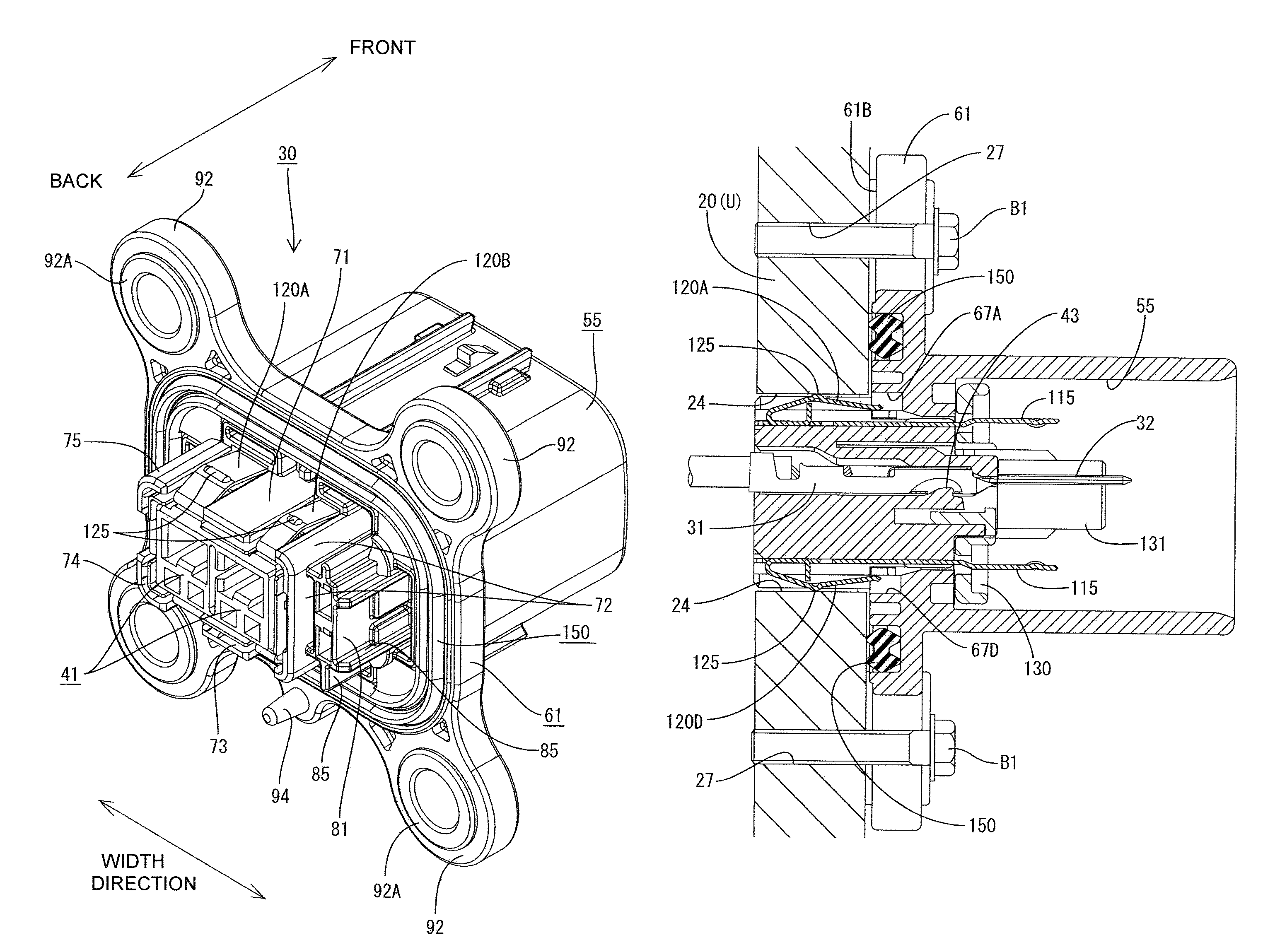
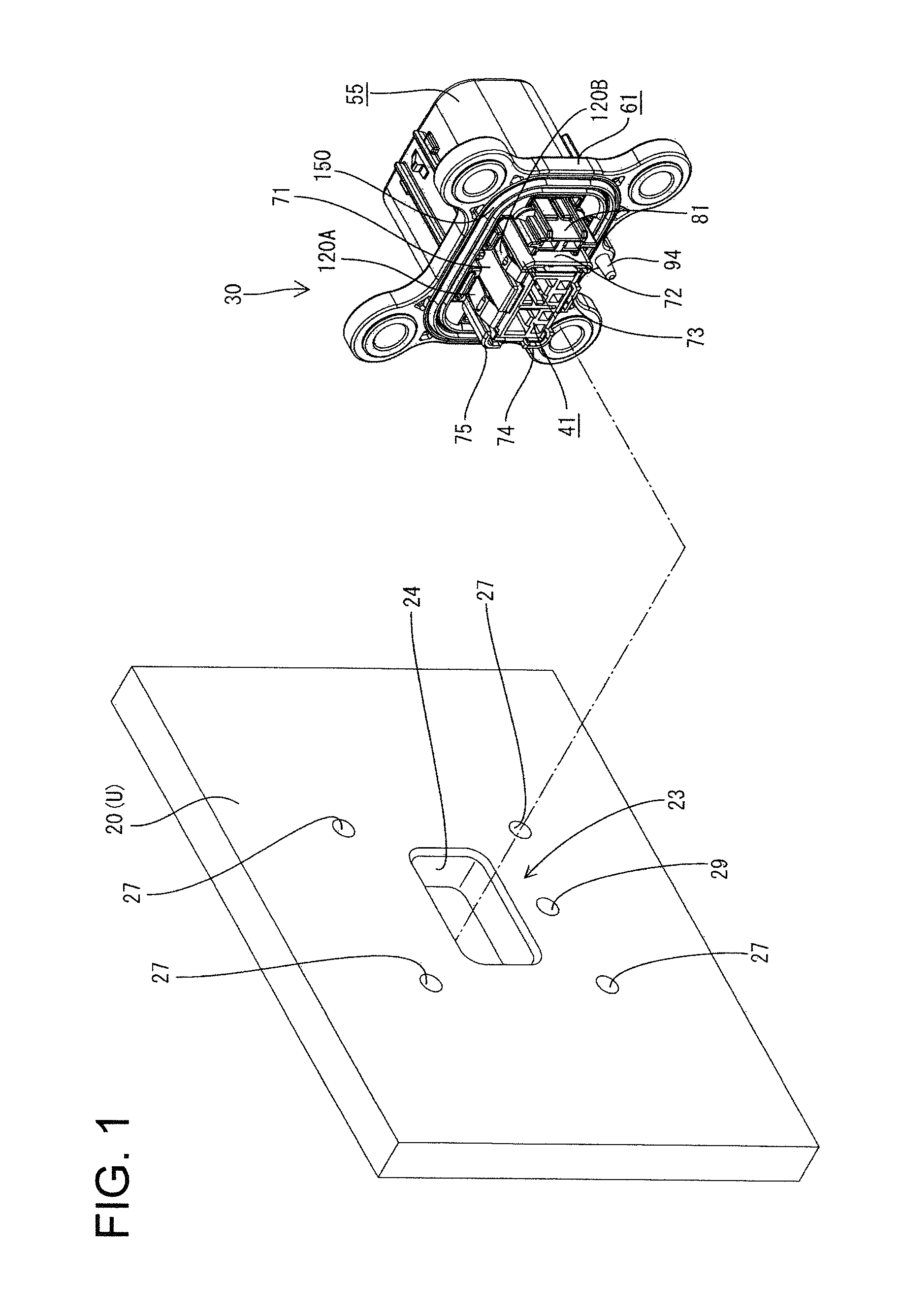
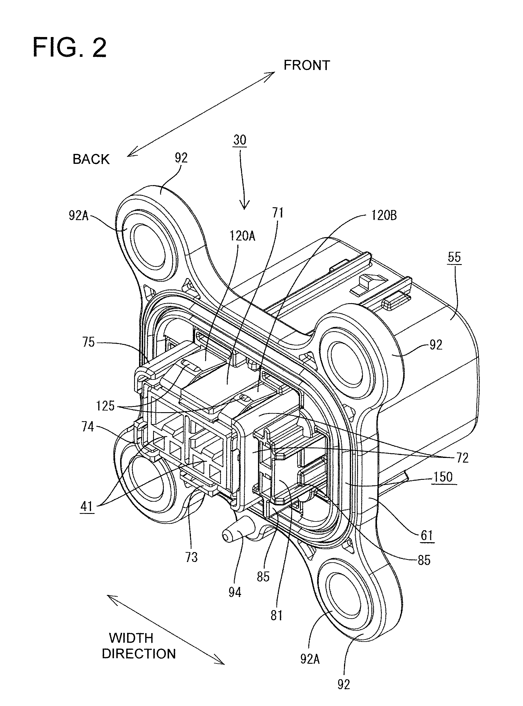
[0041]One preferred embodiment of the invention is described with reference to FIGS. 1 to 20. This embodiment is designed for directly mounting a shield connector 30 on a housing case U of an electrical device (such as an automatic transmission, junction box or the like) that may be mounted in an electrical vehicle. The housing case U is, for example, made of aluminum alloy and is box-shaped. An outer peripheral wall of the housing case U defines a mounting wall 20 on which the shield connector 30 is to be mounted.

[0042]As shown in FIG. 1, a shaft hole 23 penetrates the mounting wall 20 of the housing case U. The shaft hole 23 defines a wide rectangle with rounded corners. Bolt holes 27 and a positioning hole 29 are formed around the shaft hole 23. The bolt holes 27 are formed at positions substantially corresponding to the corners of the shaft hole 23 and the positioning hole 29 is formed below or at a side of the shaft hole 23.

[0043]In the following description, forward and backwa...


PUM


Abstract

A shield connector (30) has a housing (40) with a terminal mounting portion (41), a receptacle (55) and a mounting flange (61). Male terminals (31) are mounted in the terminal mounting portion (41) and have tabs that project into the receptacle (55). A shield shell (100) including a shell main body (110) and resilient contact pieces (120) for grounding the shell main body (110) to a mounting member. The resilient contact pieces (120) have leading ends (121) accommodated in accommodating portions (67) formed in the mounting flange (61), and the housing (40) includes protection walls (70) located lateral to the resilient contact pieces (120).

Description

BACKGROUND OF THE INVENTION[0001]1. Field of the Invention[0002]The invention relates to a shield connector to be mounted on a case of an electrical device.[0003]2. Description of the Related Art[0004]Shield connectors directly connected to metal cases of devices are widely used, for example, in electrical vehicles and the like. A metallic shield shell of a shield connector needs to be grounded to a metal case. U.S. Pat. No. 6,554,623 discloses a structure for grounding a shield shell to a metal case by bringing resilient contact pieces formed on the shield shell into contact with a hole wall of a shaft hole of the metal case. However the resilient contact pieces of the structure shown in U.S. Pat. No. 6,554,623 are mostly exposed to the outside when the connector is left alone. Thus, there is a possibility that the resilient contact piece is caught and damaged or deformed when the connector is carried around or assembled.[0005]The invention was developed in view of the above situat...

Claims


Application Information

Patent Timeline
Patent Type & Authority Patents(United States)
IPC IPC(8): H01R13/648
CPCH01R13/6596H01R13/748H01R13/745H01R2201/26
Inventor FUJIWARA, MICHIYOOKAMOTO, MASAKI
Owner SUMITOMO WIRING SYST LTD
Why Eureka
Try Eureka