Drainage stent and associated method

a technology of stent and stent body, which is applied in the field of stent, can solve the problems of limiting the technology of stent, affecting the function of stent, and proximal complications, and achieves the effect of limiting complications and facilitating fluid flow

Active Publication Date: 2012-09-11
MERIT MEDICAL SYST INC
View PDF60 Cites 10 Cited by
  • Summary
  • Abstract
  • Description
  • Claims
  • Application Information

AI Technical Summary

Benefits of technology

[0010]The invention addresses the above needs and achieves other advantages by providing a stent for a bifurcated lumen. The stent includes a drainage region that is positioned proximate to a branch of the bifurcated lumen. The drainage region includes drainage holes that facilitate fluid flow between the branch and the interior region of the stent. As such, fluid may flow in or out of the drainage holes thereby limiting complications resulting from occluding a branch lumen. A portion of the stent is also capable of being positioned adjacent to a target area within a second branch of the bifurcated lumen for supporting the target area.
[0011]In one embodiment of the present invention, a stent for facilitating flow between a branch of a bifurcated lumen and an interior region of the stent is provided. The stent includes proximal and distal ends and an interior region defined therethrough. The stent typically includes scaffolding having a cover applied thereto. The stent also includes at least one drainage region having at least one drainage hole defined between the scaffolding and through the cover such that fluid is capable of flowing through the drainage hole. The drainage region is typically offset from the proximal and / or distal end to facilitate fluid flow between the branch of the bifurcated lumen and the interior region of the stent.

Problems solved by technology

Vascular as well as nonvascular stenting has evolved significantly; unfortunately, there remain significant limitations with respect to the technology for stents implanted proximate to a bifurcated lumen within various portions of a patient's anatomy.
Furthermore, complications may arise proximate to a bifurcation that require stenting, such as within the bile duct between the hepatic ducts and the duodenum.
Providing a bifurcated stent, such as that described above, is typically difficult to position within each of the hepatic ducts.
Moreover, if a stent is positioned within one of the hepatic ducts and along the bile duct, the unstented hepatic duct may be adversely affected, such as by limiting or eliminating the flow of bile between the unstented hepatic duct and the common hepatic duct and bile duct.
In addition, similar complications may arise where a stent extends between a hepatic duct and the duodenum and across the opening of the cystic duct.

Method used


Image

  • Drainage stent and associated method
  • Drainage stent and associated method
  • Drainage stent and associated method

Examples


Embodiment Construction

[0022]The present invention now will be described more fully hereinafter with reference to the accompanying drawings, in which some, but not all embodiments of the invention are shown. Indeed, this invention may be embodied in many different forms and should not be construed as limited to the embodiments set forth herein; rather, these embodiments are provided so that this disclosure will satisfy applicable legal requirements. Like numbers refer to like elements throughout.

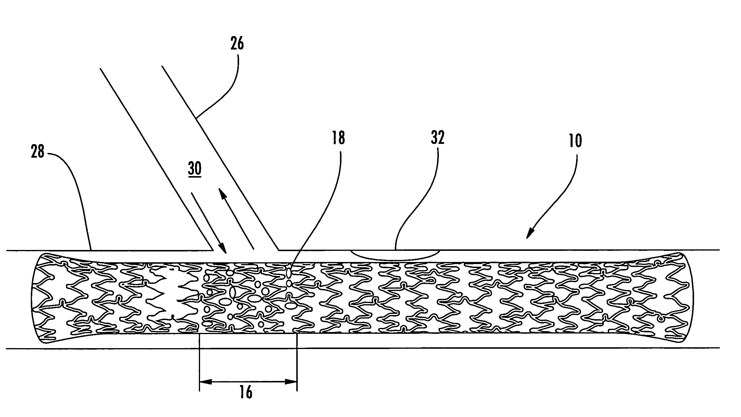
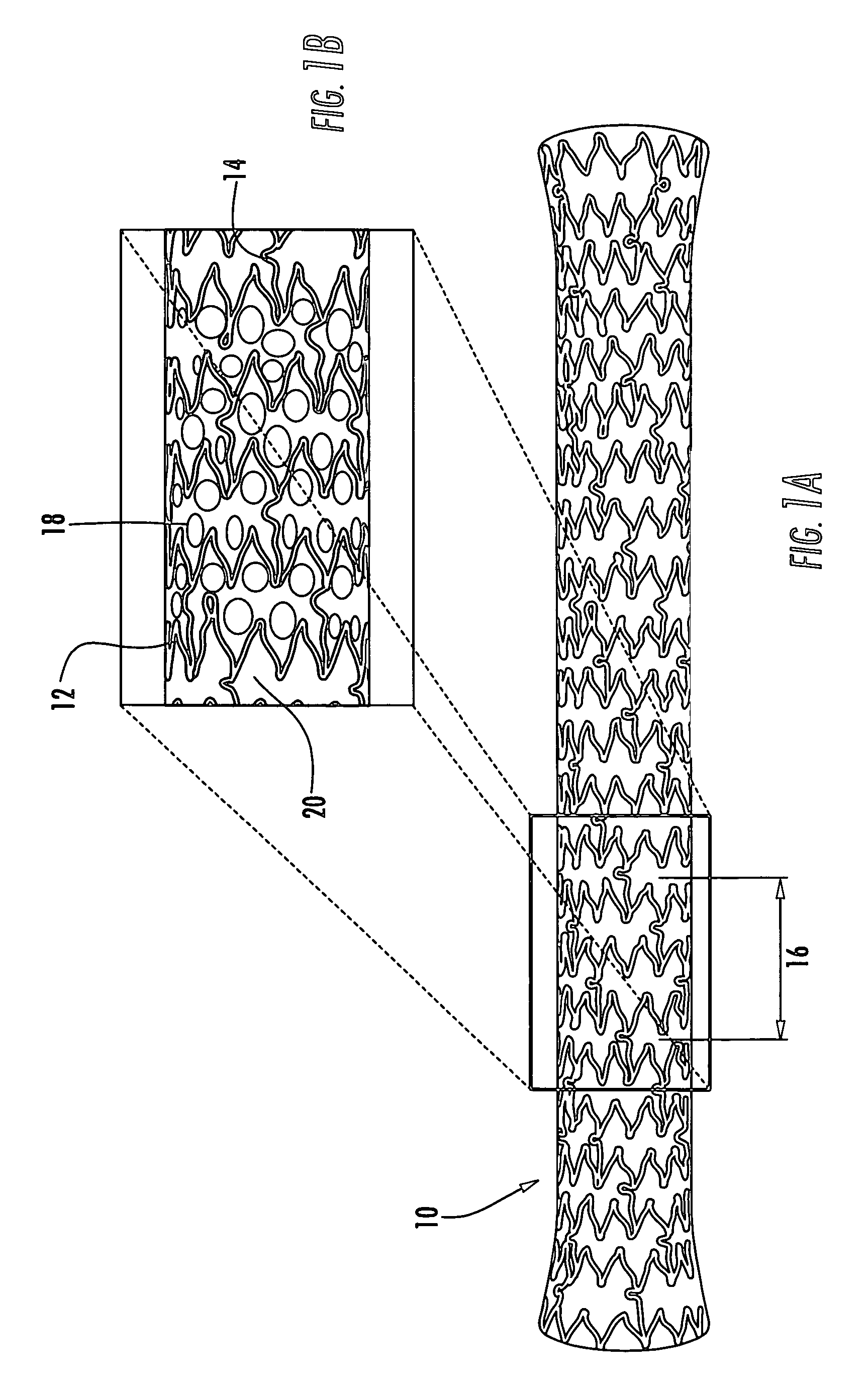
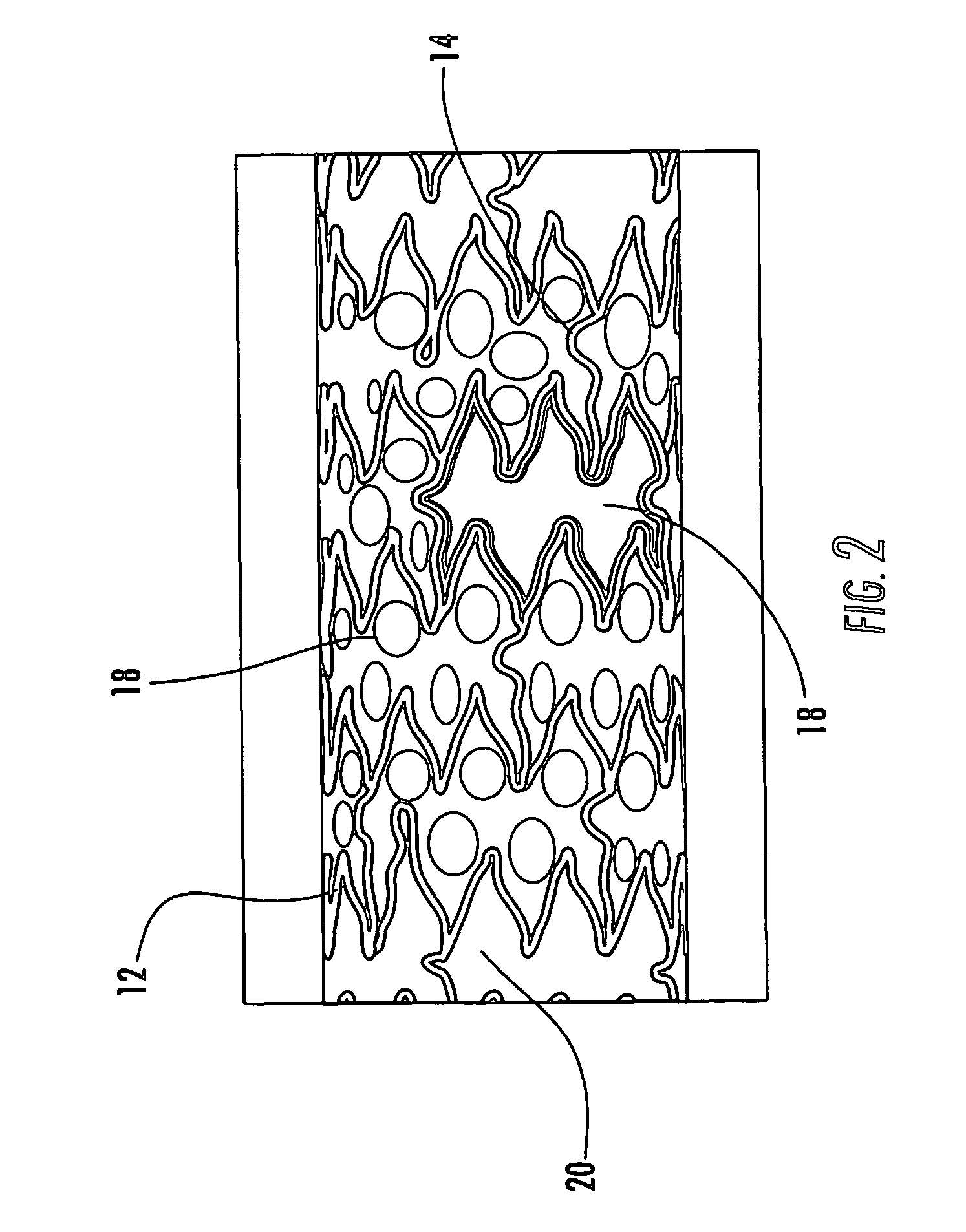
[0023]With reference to FIGS. 1A-B, a stent 10 is shown having interstice geometry. The stent 10 includes a scaffolding of struts having a plurality of interconnected legs 12 and connectors 14. In particular, the stent 10 includes a series of legs 12 arranged circumferentially about the stent, as well as arranged in a series of rows along the longitudinal axis of the stent, while a plurality of connectors 14 are arranged parallel to the longitudinal axis of the stent to connect the rows together. FIG. 1A demonstra...


PUM


Abstract

A stent for facilitating flow between a branch of a bifurcated lumen and an interior region of the stent is provided. The stent includes proximal and distal ends and an interior region defined therethrough. The stent typically includes scaffolding having a cover applied thereto. The stent also includes at least one drainage region having at least one drainage hole defined between the scaffolding and through the cover such that fluid is capable of flowing through the drainage holes. The drainage region is typically offset from the proximal and / or distal end to facilitate fluid flow between the branch of the bifurcated lumen and the interior region of the stent.

Description

CROSS-REFERENCE TO RELATED APPLICATIONS[0001]The present application claims priority U.S. Provisional Application No. 60 / 680,675 entitled “Drainage Stent and Associated Method,” filed May 13, 2005, the contents of which are incorporated herein by reference.BACKGROUND OF THE INVENTION[0002]1) Field of the Invention[0003]The present invention relates to a stent and, in particular, to a stent that is capable of facilitating fluid flow between a bifurcated lumen and the stent.[0004]2) Description of Related Art[0005]Stents are devices that are inserted into body lumina such as vessels or passages to keep the lumen open and prevent closure due to a stricture, external compression, or internal obstruction. In particular, stents are commonly used to keep blood vessels open in the coronary arteries, and they are frequently inserted into the ureters to maintain drainage from the kidneys, the bile duct for pancreatic cancer or cholangiocarcinoma, or the esophagus for strictures or cancer. Vas...

Claims


Application Information

Patent Timeline
Patent Type & Authority Patents(United States)
IPC IPC(8): A61F2/06
CPCA61F2/07A61F2/856A61F2/915A61F2002/072A61F2230/0013A61F2002/91533A61F2002/91575A61F2002/91583A61F2250/0098A61F2002/91508
Inventor WELBORN, KRISTINNISSL, THOMAS
Owner MERIT MEDICAL SYST INC
Why Eureka
Try Eureka