
Route search system

a search system and route technology, applied in the field of route search system, can solve the problem that the search of the optimum route where the fare is controlled cannot be implemented

Active Publication Date: 2012-09-11
MEL NAVIP LLC
View PDF29 Cites 3 Cited by
  • Summary
  • Abstract
  • Description
  • Claims
  • Application Information

AI Technical Summary

Benefits of technology

"The present invention is a route search system that allows users to search for the best route to their destination while controlling fares. The system includes a map data storing means that stores a roadmap data with information about which roads are within a flat-rate pay area where a fixed fare is charged on a mobile unit transiting the area. The system also includes a position detecting means to detect the current position of the mobile unit, a flat-rate pay area transit recording means to record that the mobile unit has transited the flat-rate pay area, an input means to decide whether to allow the transit of the flat-rate pay area, and a route calculating means to calculate the optimum route to the destination based on the roadmap data and the input of the user. The technical effect of this invention is that users can easily search for the best route while controlling fares, and the system can provide them with the most efficient route to their destination."

Problems solved by technology

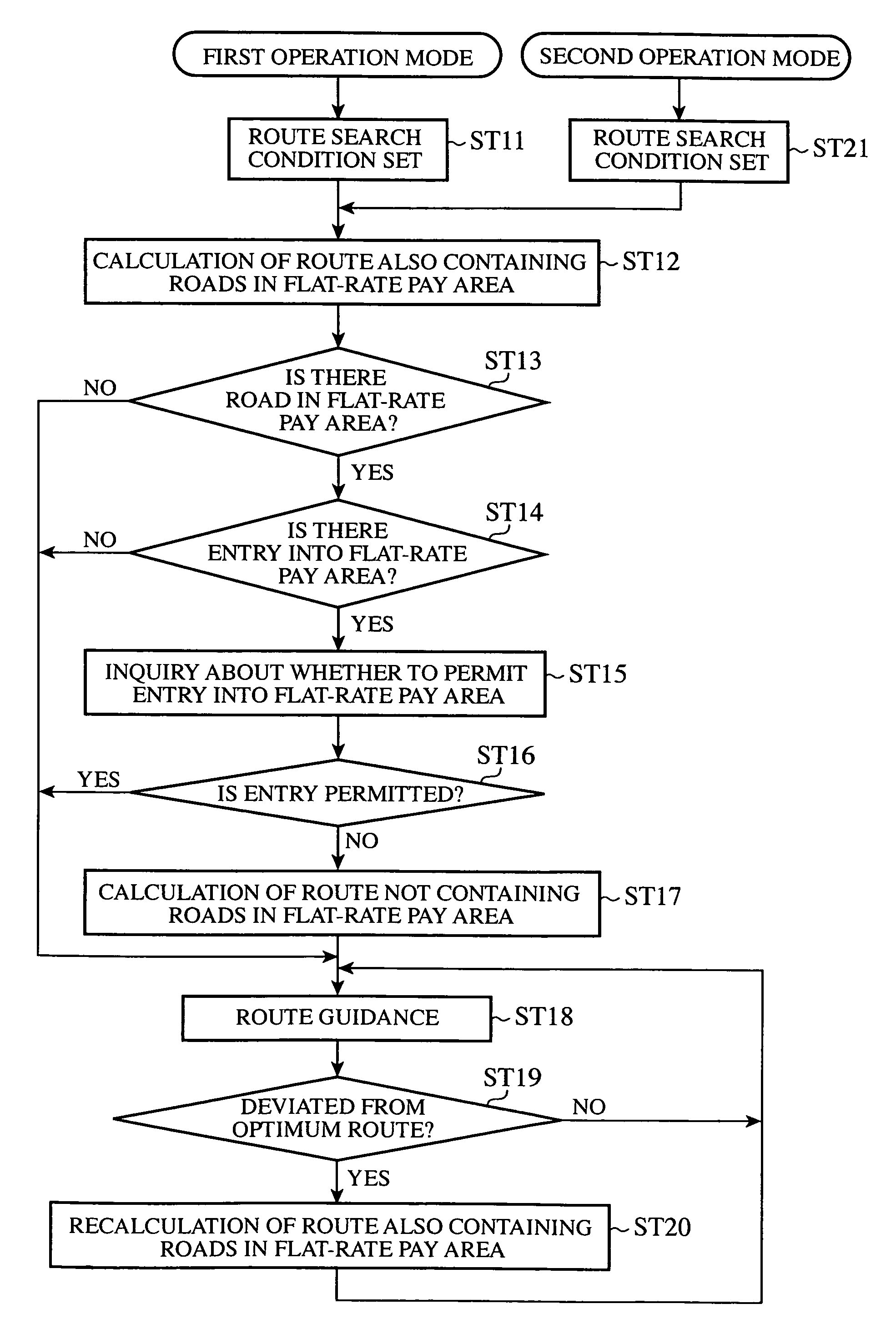
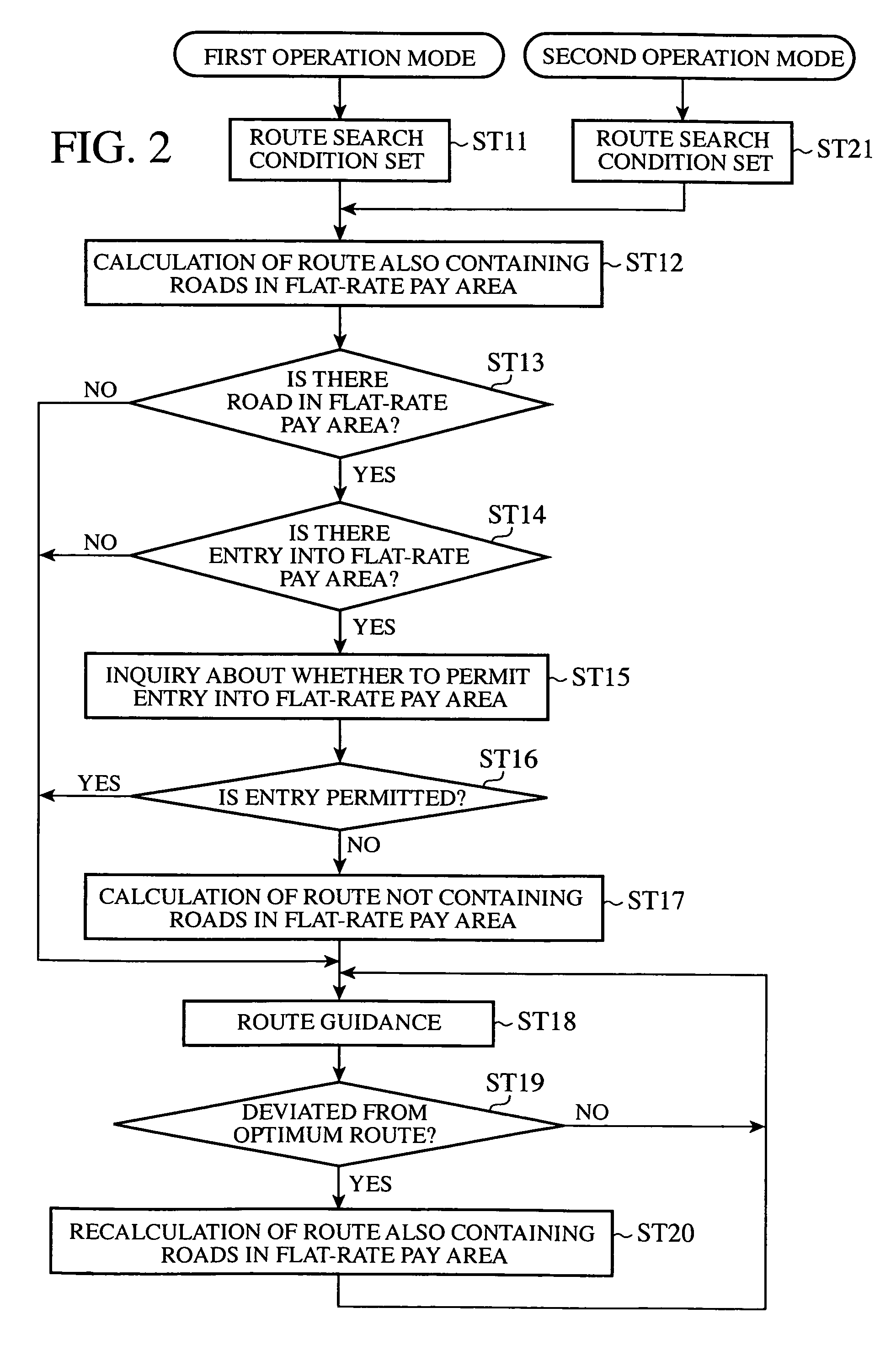
The route search system disclosed in Patent Document 1 as mentioned above is effective in saving the fare charged to a user in a system charging the user by the number of times the user takes a uniform-rate pay area; however, as in the case of the road pricing system of London, in the case of a system where the amount of money charged is fixed per day and a fixed fare is charged regardless of the number of times a mobile unit enters the area if the entries are made within the fixed period of time, there is a problem that a search of the optimum route where the fare is controlled cannot be implemented.

Method used


Image

  • Route search system
  • Route search system
  • Route search system

Examples


first embodiment

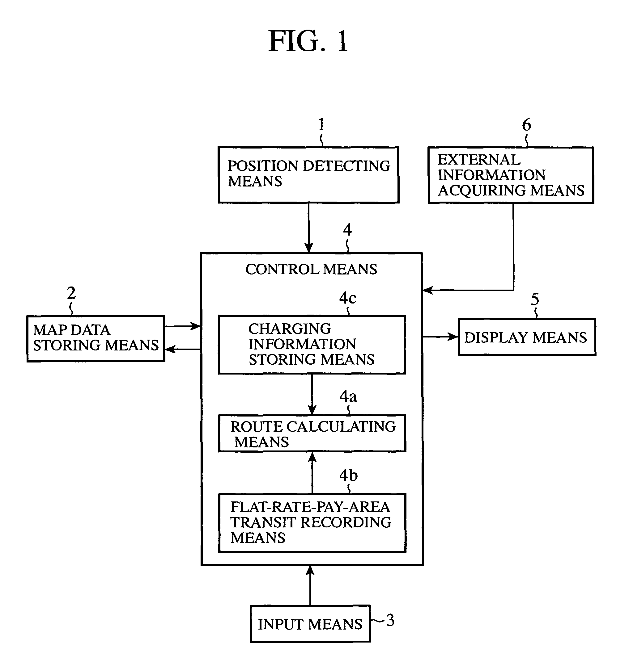
[0014]FIG. 1 is a block diagram showing the configuration of a route search system in accordance with the first embodiment of the present invention. The route search system is composed of a position detecting means 1, a map data storing means 2, an input means 3, a control means 4, a display means 5, and an external information acquiring means 6.

[0015]The position detecting means 1 is composed of, for example, a GPS (Global Positioning System), a gyro sensor, and a speed sensor and so on, and detects a user's current position. The user's current position detected by the position detecting means 1 is transmitted to the control means 4 as current position data.

[0016]The map data storing means 2 is composed of a storage medium such as a DVD (Digital Versatile Disk) and a HDD (Hard Disk Drive), and stores roadmap data. The roadmap data is provided with attribute information showing whether the road indicated by the roadmap data is a road located within a flat-rate pay area. In this conn...


PUM


Abstract

A route search system includes a map data storing means 2 storing a roadmap data containing, as the attribute of a road, whether the road is a road located within a flat-rate pay area where a fixed fare is charged on a mobile unit regardless of the number of times the mobile unit enters the area if the entries are made within a fixed time period; a flat-rate pay area transit recording means 4b, when the current position detected by a position detecting means 1 comes to a road in the flat-rate pay area represented by the attribute of the roadmap data stored in the map data storing means, storing that the mobile unit has transited the flat-rate pay area; an input means 3 inputting whether to permit transit across the flat-rate pay area; and a route calculating means 4a, when it is inputted by the input means that the transit thereof is not permitted, if the flat-rate pay area transit recording means stores that the mobile unit has transited the flat-rate pay area, calculating the optimum route to the destination within routes also containing roads located within the flat-rate pay area on the basis of the roadmap data stored in the map data storing means.

Description

Cross Reference to Related Applications:[0001]This nonprovisional application claims the benefit of U.S. Provisional Application No. 2006-006601 filed on Jan. 13, 2006 and of Japanese Patent Application No. 2007-553829 filed in Japan, on Mar. 5, 2008. The entire contents of all of the above applications is hereby incorporated by reference.TECHNICAL FIELD[0002]The present invention relates to a route search system making a search for the optimum route from a current position to a destination, and more particularly to a technology for making a route search by controlling a toll charged in an area where a pay area of a flat-rate system is established (hereinafter referred to as a “flat-rate pay area”).BACKGROUND ART[0003]Conventionally, there has been known a route search system making a route search by controlling the tolls of toll roads, and so on. For example, Patent Document 1 discloses a route search system capable of preventing anew using the same line within a flat-rate toll roa...

Claims


Application Information

Patent Timeline
Patent Type & Authority Patents(United States)
IPC IPC(8): G01C21/34
CPCG01C21/3461G08G1/096827G08G1/096838
Inventor ARITA, HIDEKAZUOHI, MAKOTO
Owner MEL NAVIP LLC
Learn More