Clip for fabrics

a fabric and clip technology, applied in the field of fabric clip, can solve the problems of affecting the movement of fabrics, affecting the appearance of fabrics, and affecting the appearance of fabrics, and achieve the effect of preventing the movement of fabrics

Inactive Publication Date: 2012-09-18
TECCO
View PDF37 Cites 4 Cited by
  • Summary
  • Abstract
  • Description
  • Claims
  • Application Information

AI Technical Summary

Benefits of technology

[0044]It is yet another object of this invention is to provide a plastic clip having a large area of a contoured tortuous frictional surface to prevent the fabric from moving or sliding, to distribute the clamping force of the clip and impede movement of the fabric.

Problems solved by technology

However, such a metal clip is relatively expensive to manufacture.
An adhesive backed badge is undesirable because it can only be used once and can damage certain type fabrics.
Pinning a name badge to clothing, although used for many years, can puncture and tear delicate fabrics and presents difficulties in maintaining the badge, in the proper orientation.
Additionally, the sharp point of the pin can stick and injure people, creating a health hazard.
In hospitals and other environments, pin badges are not acceptable because a puncture of the skin can cause an infection or a contagious situation, e.g., HIV.
The badge is usually twirling, too high, or too low making it difficult to read as well as presenting anatomical difficulties for many females and / or an embarrassment for most men.

Method used


Image

  • Clip for fabrics
  • Clip for fabrics
  • Clip for fabrics

Examples


first embodiment

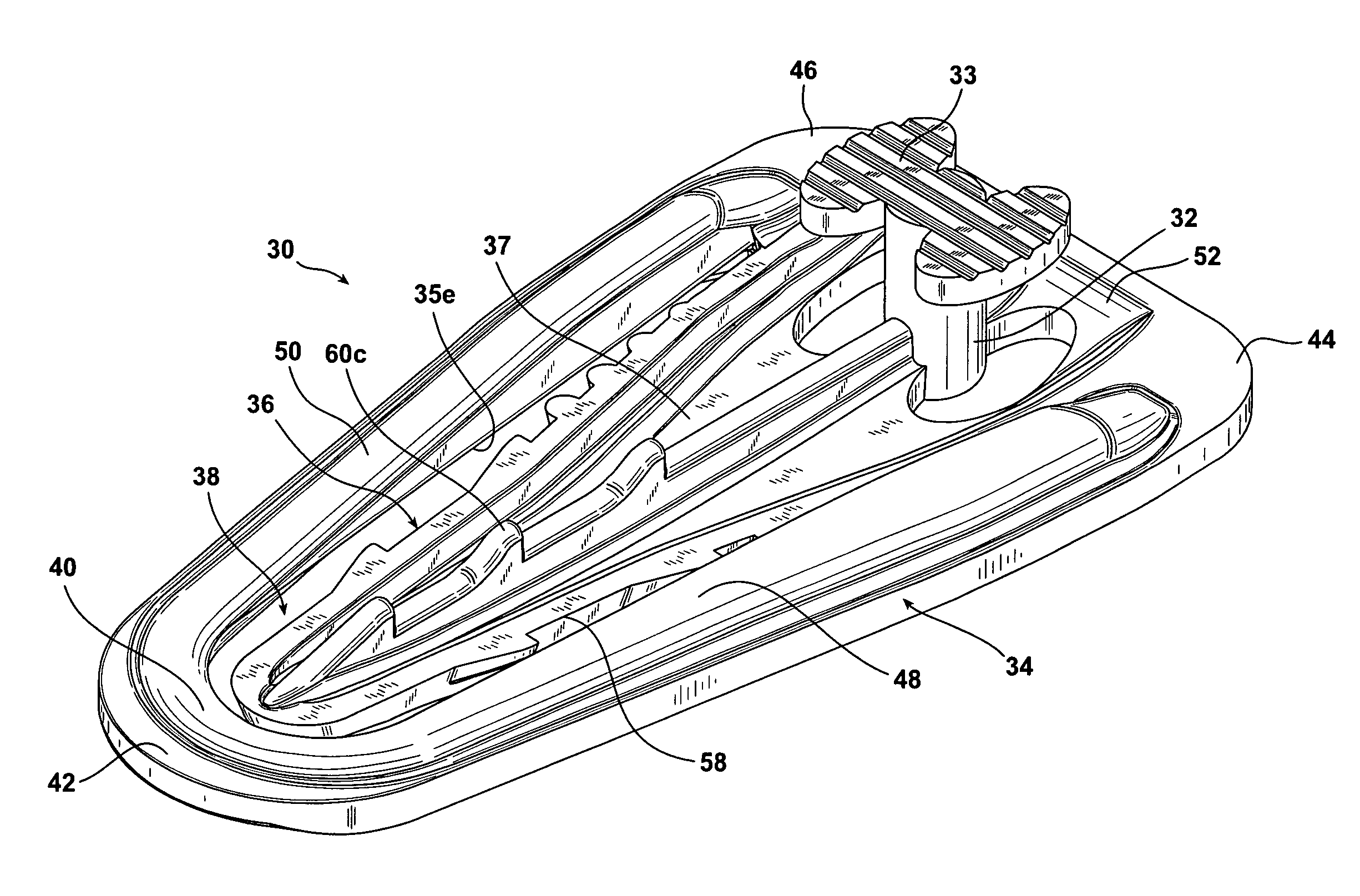
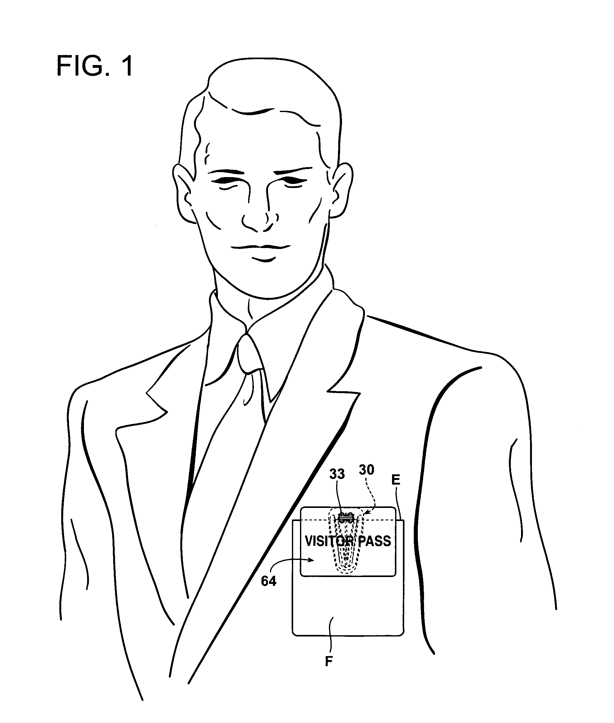
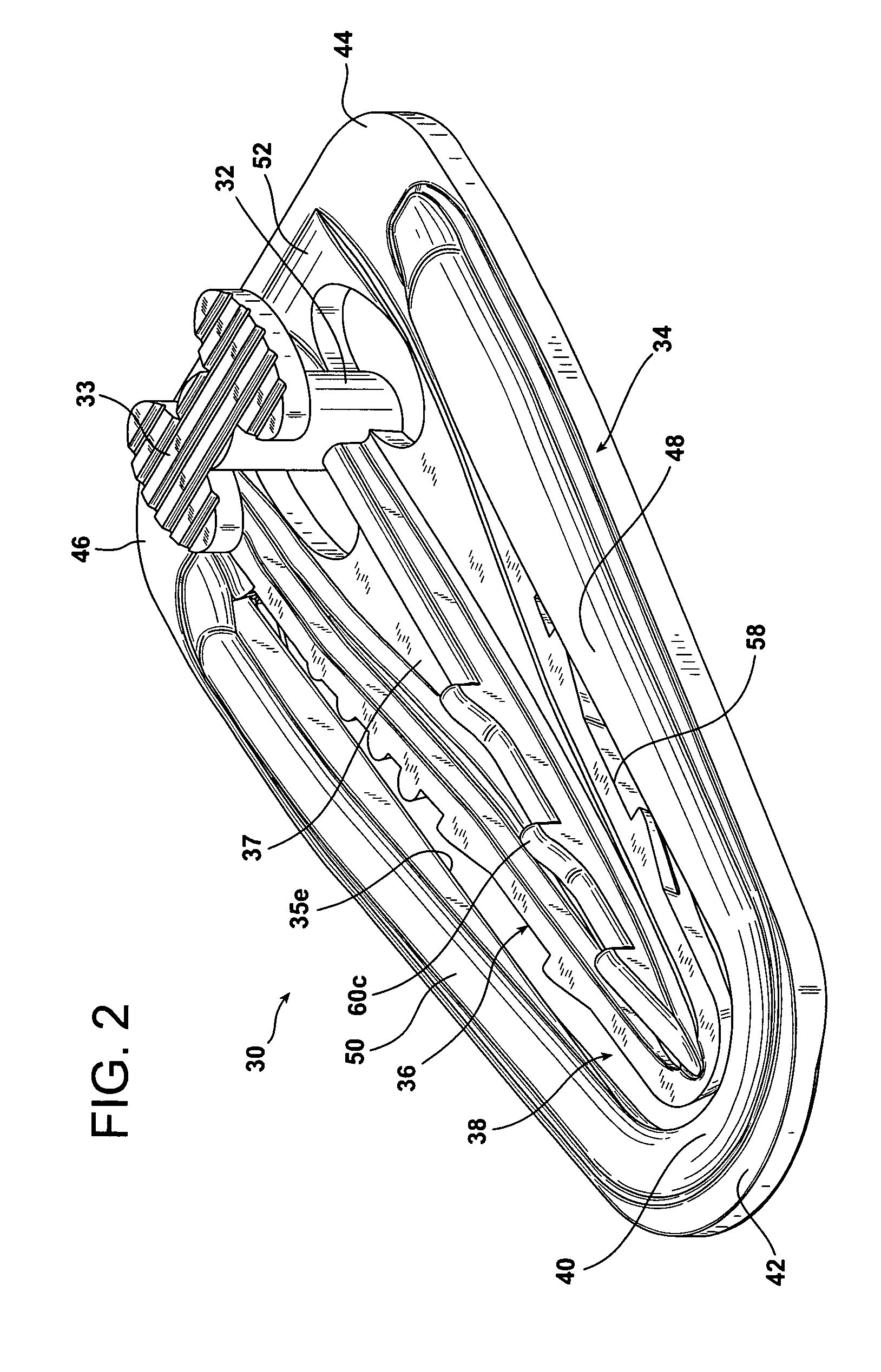
[0069]FIGS. 1-9 depict the clip in the form of a badge clip 30. The clip 30 is a unitary, one piece plastic-molded clip and includes a substantially planar clip body 34 that has a front 35f (FIG. 5) and rear 35r (FIG. 5) surface and side edges 35e. The clip body 34 has an opening 38 therein passing through the front 35f and rear surfaces 35r to form a periphery structure 40 having an interior wall 56 (FIG. 4) surrounding the opening 38. A badge post 32, preferably cylindrical, is mounted to the periphery structure 40 at one end of the clip body 34, designated herein as the top 52 of the clip 30.

[0070]Referring to FIGS. 1-9, a substantially planar flexible central spring member 36 is provided having front 37 and rear 39 surfaces and a surrounding edge surface 58. The spring member 36 appends from a top portion 52 of the periphery structure 40. The spring member 36 is springedly mounted to the periphery structure 40 near the badge post 32 and suspended within the opening 38. The sprin...

second embodiment

[0089]FIG. 10 is a front plan view of the clip 80 of this invention. In this embodiment the badge post on the top 52 of the periphery structure 40 is not present and in its stead is a string or string or lanyard attachment hole 82 to permit the clip 80 to hang freely from, for example, from the neck of the user while the clip 80 grasps, for example, a speaker's ribbon, a napkin, etc.

[0090]FIG. 11 is a front plan view of a third embodiment 90 of the clip of this invention. In this embodiment the top portion 52 of the periphery 40 has an extended planar surface 92. This permits the placement of a badge (not shown) on the badge post 32 and the placement of an indicia, e.g., a company name, an advertisement, etc. on the extended planar surface 92.

[0091]FIGS. 12, 13 and 14 are front plan views of different variations of a fourth embodiment 100 of the clip of this invention. In this embodiment the top portion of the periphery 40 has an extended planar surface 102. This embodiment eliminat...


PUM


Abstract

A badge holder for attachment to a garment includes a planar clip body having an opening therein forming a periphery structure in the clip body. A planar flexible spring member appends from a top portion of the periphery structure, with the free end terminating within the opening near a bottom portion of the structure and is coplanar therewith. The gap between the edge surface of the spring member and the interior wall of the periphery structure decreases in width from the bottom portion of the peripheral structure to the top portion of the peripheral structure. A plurality of projecting elements project from the surrounding edge surfaces of the spring member and from the front surface to assist in firmly holding the fabric in the clip. A badge mounting member projects from the front surface of the periphery structure upon which a badge can be mounted.

Description

RELATED APPLICATIONS[0001]This application is a Continuation-In-Part of U.S. Ser. No. 29 / 370,645 (3.1-006) and US Serial No. 29 / 370,646 (3.1-007) both filed on Aug. 18, 2010 and both entitled Clip For Identification Badges, now U.S. Pat. Nos. D631,737 and D631,738, respectively, both issued on Feb. 1, 2011.BACKGROUND OF THE INVENTION[0002]1. Field of the Invention[0003]The invention relates to a unitary, one piece clip, preferably intended for attaching badges and other display items to garments, which safely and securely attaches the display item to a fabric, e.g., jacket pocket, or other flexible material.[0004]2. Related Art[0005]A badge clip is a clamping device to which a badge is attached and which is then clamped onto the users apparel. Typically such a clip is made of metal or plastic and employs jaws that open and close, and when closed, capture a narrow piece of the wearer's apparel. The jaw portion of the clip that actually grasps the fabric is usually a very narrow edge ...

Claims


Application Information

Patent Timeline
Patent Type & Authority Patents(United States)
IPC IPC(8): A45F5/04B42F1/12A43C3/00F16B2/20B42F1/10
CPCG09F3/16G09F3/207F16B2/22Y10T24/1394Y10T24/44017Y10T24/1374Y10T24/1312
Inventor HAAS, DAVID J.
Owner TECCO
Why Eureka
Try Eureka