Cable guiding device

a guiding device and cable technology, applied in the direction of gearing elements, belts/chains/gearrings, hoisting equipment, etc., can solve the problems of reducing the service life of the cable, and damaging the cable, so as to reduce the abrasion between the cable and the guiding device. , the effect of low cost and small siz

Active Publication Date: 2012-09-18
HANGZHOU TIANMING TECH CO LTD
View PDF36 Cites 12 Cited by
  • Summary
  • Abstract
  • Description
  • Claims
  • Application Information

AI Technical Summary

Benefits of technology

[0007]The present invention overcomes at least one of the problems existing in the prior art. Accordingly, one embodiment of the present invention provides a cable guiding device that is small in size and low in cost, and the abrasion between the cable and the cable guiding device is decreased, thus prolong the service life of the cable and the cable guiding device.
[0009]With the cabling guiding device of the present invention, the upper and lower guiding rollers are rotatable relative to the upper and lower movable members respectively, the upper and lower guiding rollers and the upper and lower movable members together with the slider are movable in the longitudinal direction relative to the upper and lower guide members respectively. Therefore, during the cable being wound onto and unwound from the drum, no sliding friction occurs between the cable and the upper guiding roller as well as the lower guiding roller in the circumferential and longitudinal directions of the upper and lower guiding rollers. The cable guiding device according to one embodiment the present invention may reduce abrasion of the cable and prolong service life of the cable. Therefore, with the cable guiding device according to the embodiment of the present invention, the lengths of upper and lower guiding rollers may be reduced, and the cost and the size of the cable guiding device may be reduced as well.

Problems solved by technology

Therefore, the cable and the upper and lower guiding rollers are abraded, thus reducing the service lives thereof.
Thirdly, the cable will be loose if no load is applied to the free end of the cable during winding of the cable onto the drum, so that the cable could not be wound tidily onto the drum, thus causing the cable to be in disorder, which results in damaging the cable, reducing the service life of the cable, and even damaging the winch.

Method used


Image

  • Cable guiding device
  • Cable guiding device
  • Cable guiding device

Examples


Embodiment Construction

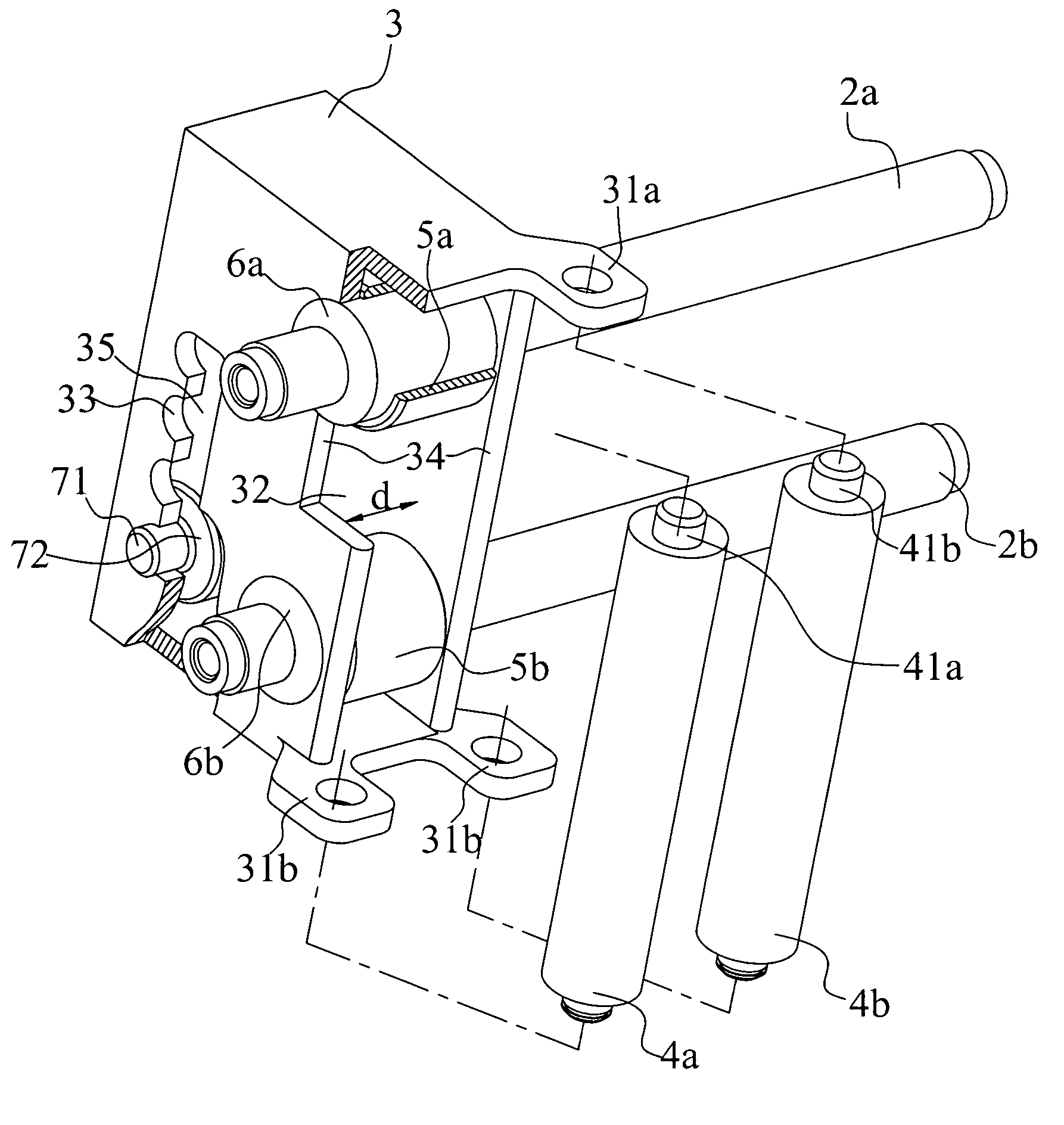
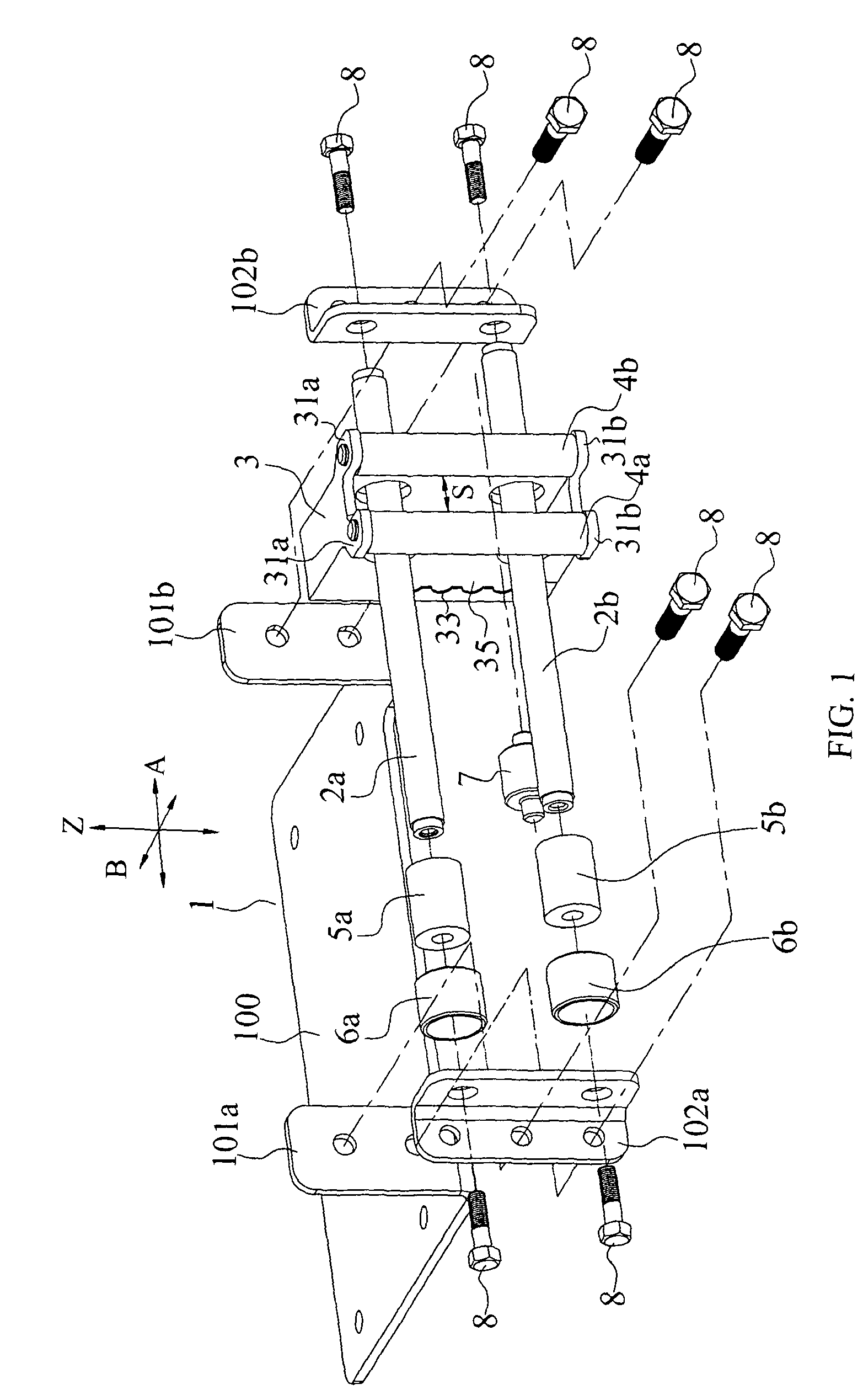
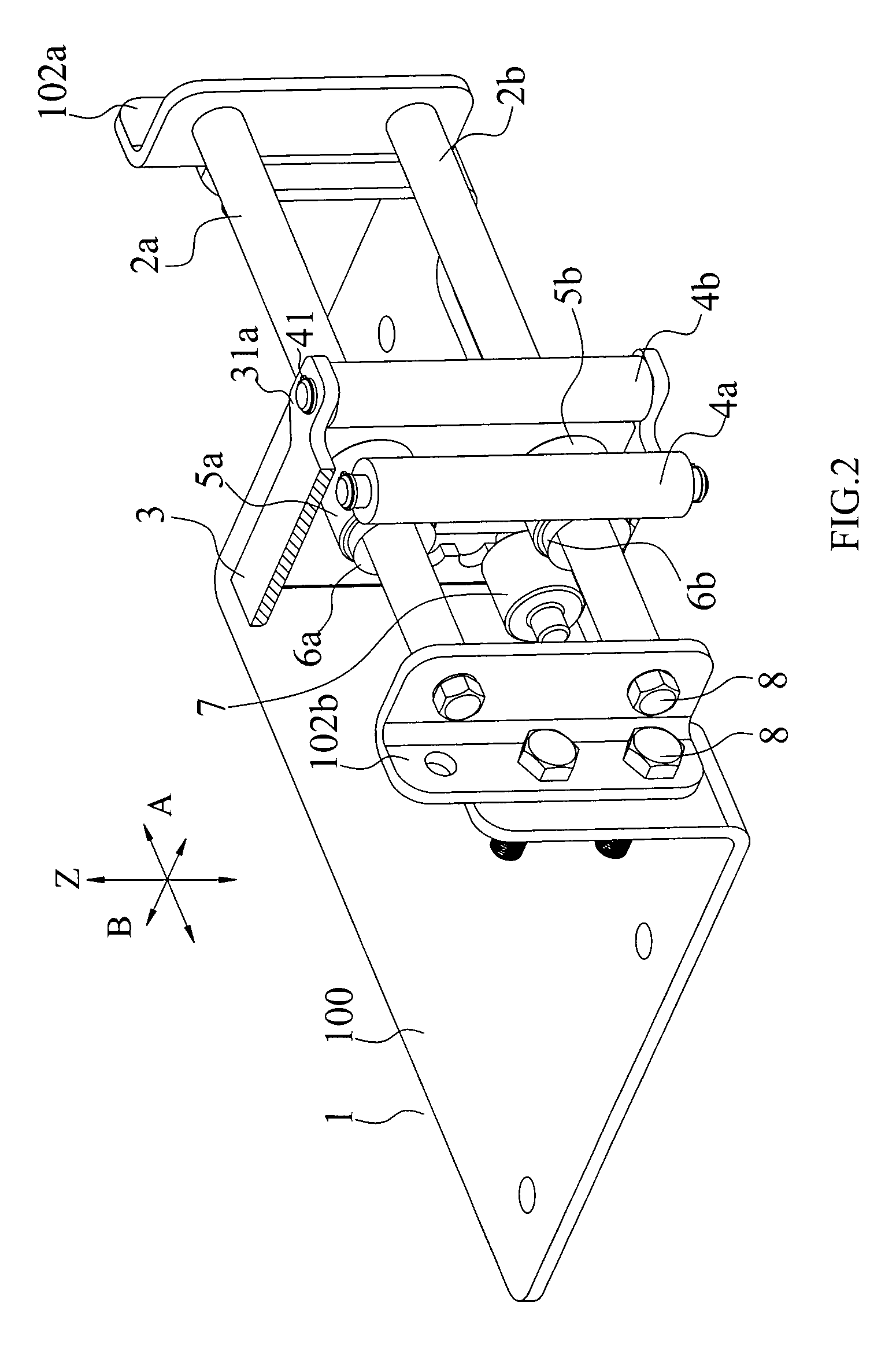
[0021]The cable guiding device according to one embodiment of the present invention will described in detail with reference to the drawings below. The embodiments described herein with reference to the drawings are explanatory, illustrative, and used to generally understand the present invention. The embodiments shall not be construed to limit the present invention. The same or similar elements and the elements having same or similar functions are denoted by like reference numerals throughout the descriptions.

[0022]In the description, relative terms such as “longitudinal”, “lateral”, “front”, “rear”, “right”, “left”, “lower”, “upper”, “horizontal”, “vertical”, “above”, “below”, “top”, “bottom” as well as derivative thereof (e.g., “horizontally”, “downwardly”, “upwardly”, etc.) should be construed to refer to the orientation as then described or as shown in the drawings under discussion. These relative terms are for convenience of description and do not require that the present inven...


PUM


Abstract

A cable guiding device includes a base, upper and lower guide members disposed along a longitudinal direction, in which two ends of the upper guide member are mounted on the base and two ends of the lower guide member are mounted on the base. A slider defining a central cavity is penetrated therethrough in a lateral direction substantially perpendicular to the longitudinal direction. Upper and lower movable members are fitted slidably over the upper and lower guide members respectively, in which two ends of the upper movable member are mounted on two longitudinal side walls of the slider, and two ends of the lower movable member are mounted on two longitudinal side walls of the slider respectively. Upper and lower guiding rollers are fitted rotatably over the upper and lower movable members and disposed within the central cavity respectively.

Description

BACKGROUND OF THE INVENTION[0001]1. Field of the Invention[0002]The present invention generally relates to a cable guiding device, more particularly, and to a cable guiding device for a winch.[0003]2. Description of the Related Art[0004]A winch is a vehicle-carried apparatus mainly used for vehicle rescue, loading or unloading, which can be mounted on a vehicle such as an engineering vehicle, an off road vehicle, and SUV sports vehicle.[0005]FIG. 8 shows a conventional cable guiding device 200. The conventional cable guiding device 200 comprises a base 203, an upper guiding roller 201 and a lower guiding roller 202 which are supported rotatably on the base 203 respectively. The cable guiding device 200 is generally disposed in front of a winch (not shown) in use, and the longitudinal direction of the cable guiding device 200 (i.e., the axial direction of the upper and lower guiding rollers 201 and 202) is substantially consistent with the axial direction of a drum of the winch. The ...

Claims


Application Information

Patent Timeline
Patent Type & Authority Patents(United States)
IPC IPC(8): B66D1/36
CPCB66D1/36B66D3/006
Inventor YANG, HUIZHONGQING, ZHAOBOBAO, WEI
Owner HANGZHOU TIANMING TECH CO LTD
Why Eureka
Try Eureka