Floor panel, as well as method, device and accessories for manufacturing such floor panel

a technology for floor panels and manufacturing methods, applied in the field of floor panels, can solve the problems of very small depth, in relation to the surface,

Active Publication Date: 2012-09-25
FLOORING IND LTD
View PDF88 Cites 65 Cited by
  • Summary
  • Abstract
  • Description
  • Claims
  • Application Information

AI Technical Summary

Benefits of technology

[0011]By applying embossed portions continuing up into the aforementioned substrate, the advantage is created that the surface, at the location of the embossed portions, is situated rather deep, as a consequence of which a better imitation of scraped wood is possible.
[0093]According to a first form of embodiment of this second possibility, an etching technique is applied, which at least consists of applying a substance that can be hardened by means of radiation, more particularly by means of light, such as UV light, preferably in the form of a gel, over the surface of the press plate to be etched; depositing a protective product, systematically and in form of a pattern, on this substance, such that certain zones become impervious to said radiation; having radiation effect in such a manner that those portions of said substance that are accessible to said radiation, are hardened; removing the un-hardened portions of said substance; and etching the press plate, whereby then substantially material is etched off the press plate at those locations where no material of said substance is present. Preferably, the aforementioned pattern is provided on the substance by means of a digitally controlled printer, the printing unit of which is moved over the substance. An advantage thereof is that the pattern can be applied very precisely.

Problems solved by technology

When the scraped-off portions then are imitated in a laminate floor by providing embossments in the laminate layer that, in depth, extend exclusively in this laminate layer, the disadvantage is created that the depth, in relation to the surface, is very small, as a result of which the intended effect is almost not noticeable.

Method used


Image

  • Floor panel, as well as method, device and accessories for manufacturing such floor panel
  • Floor panel, as well as method, device and accessories for manufacturing such floor panel
  • Floor panel, as well as method, device and accessories for manufacturing such floor panel

Examples


Embodiment Construction

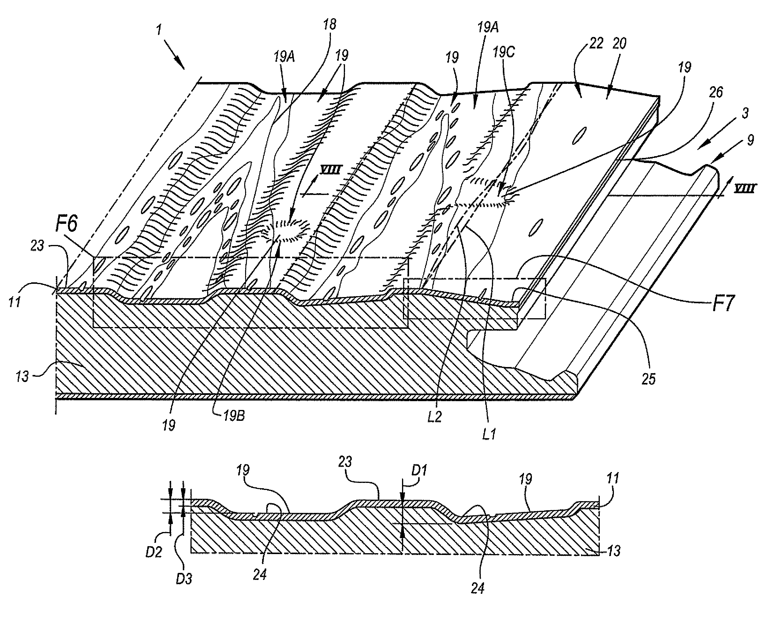
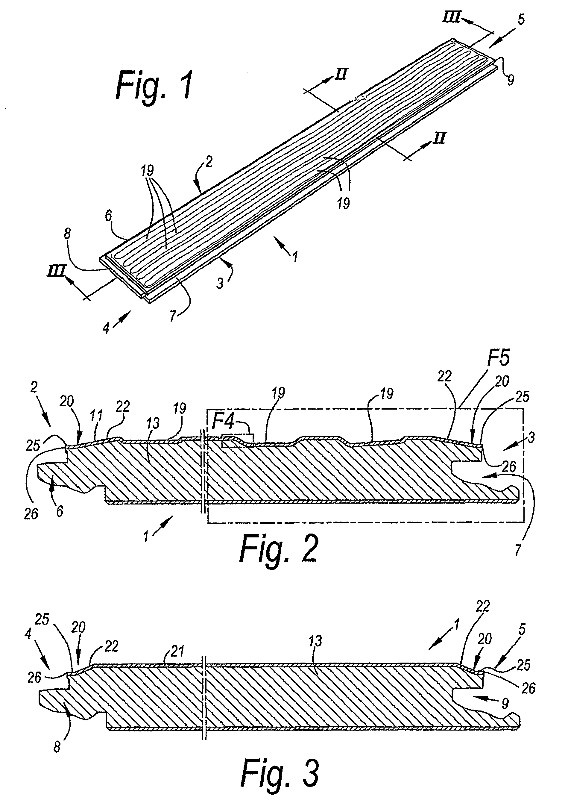
[0123]As represented in FIG. 1, the invention relates to a floor panel 1 of the type intended for forming a floating floor covering.

[0124]This floor panel 1 is provided, at two opposite edges 2-3, and even better, as represented in FIGS. 2 and 3, at both pairs of opposite edges 2-3 and 4-5, with coupling parts 6-7 and 8-9, with which several of such floor panels 1 can be coupled to each other. As represented, these coupling parts 6-7 and / or 8-9 preferably are of the type, which, in coupled condition of the floor panels 1, effects a locking in vertical and horizontal directions.

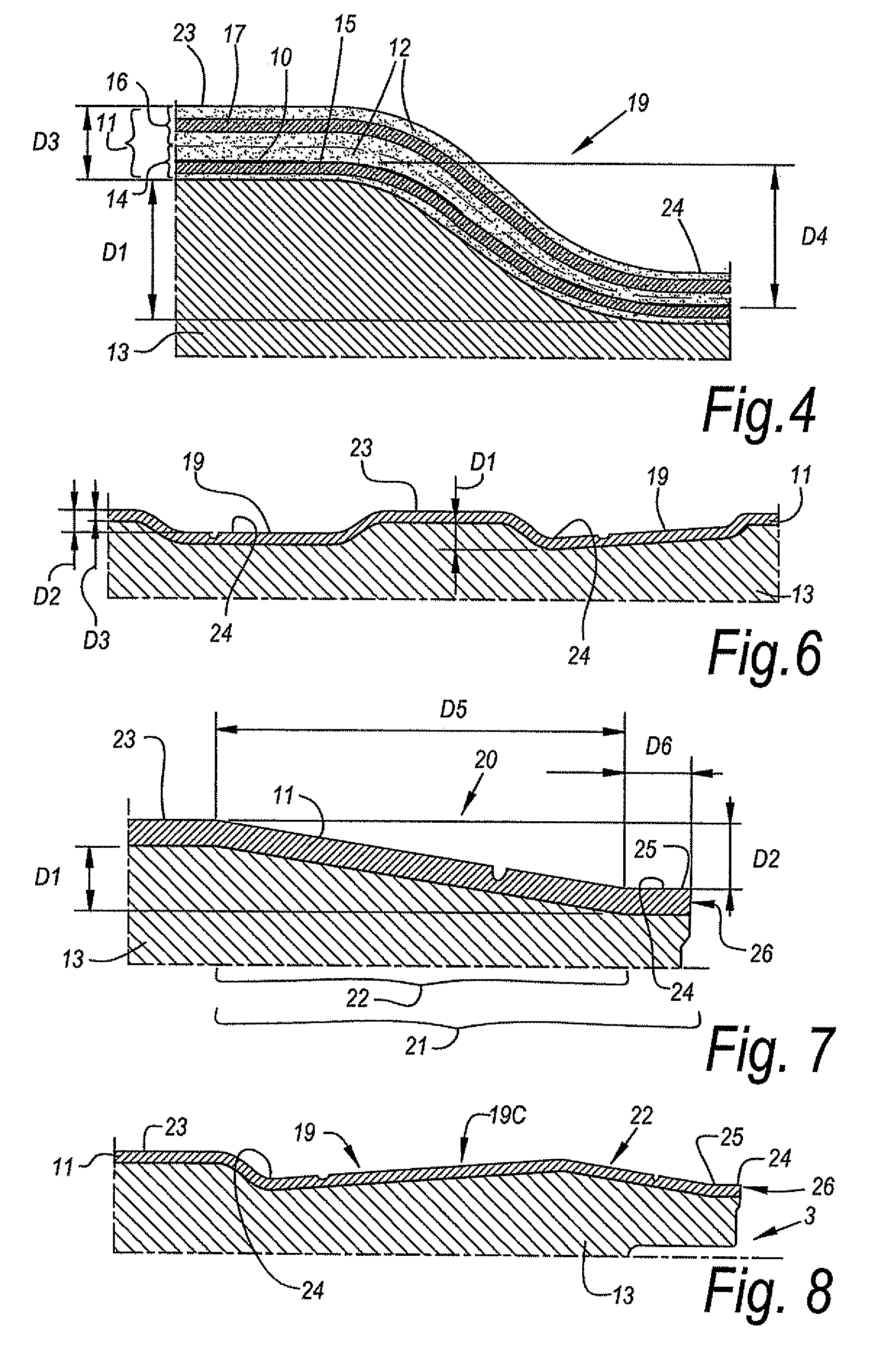
[0125]As represented in FIG. 4, the floor panel 1 comprises at least a decor 10 and a top layer 11, also called laminate layer, on the basis of synthetic material 12, as well as an underlying substrate 13.

[0126]In the represented example, the top layer 11 is performed as a DPL laminate that, as is represented in greater detail, however, in a schematic manner, in FIG. 4, is formed of two layers pressed upon eac...


PUM

PropertyMeasurementUnit
distanceaaaaaaaaaa
distanceaaaaaaaaaa
distanceaaaaaaaaaa

Abstract

Floor panel, more particularly a laminate floor panel, wherein this floor panel comprises a decor, a top layer on the basis of synthetic material, and an underlying substrate (13), whether or not composed of several layers or parts, wherein the floor panel (1), in the surface over which the decor (10) extends, is provided with embossed portions.

Description

[0001]This application is a continuation of U.S. application Ser. No. 11 / 315,290, filed Dec. 23, 2005, which claims the benefit of U.S. provisional patent application 60 / 690,866, filed Jun. 16, 2005 under 35 U.S.C. 119(e) of which the full contents of the provisional application is incorporated in this application by reference.BACKGROUND[0002]A. Field[0003]This invention relates to a floor panel, as well as a method, a device and accessories for manufacturing such floor panel.[0004]B. Related Art[0005]Thereby, it also relates to a number of methods that can be applied indirectly in the manufacturing process of the floor panels, such as etching techniques, which are particularly suited for realizing press plates that can be applied when manufacturing floor panels, whereby these etching techniques, according to the present invention, however, are not limited to this field of application.[0006]More particularly, the invention relates to floor panels of the type which, at least at two o...

Claims


Application Information

Patent Timeline
Patent Type & Authority Patents(United States)
IPC IPC(8): E04B1/00B27M1/00B27H1/00E04D1/00E04G21/00E04G23/00
CPCB44C1/24B44C3/005B44C3/08B44C5/0469E04F15/02E04F15/02033B44F9/02E04F2201/026E04F2201/0115E04F2201/0153E04F15/02038E04F15/02161
Inventor MEERSSEMAN, LAURENTVANDEVOORDE, CHRISTIANTHIERS, BERNARD
Owner FLOORING IND LTD
Why Eureka
Try Eureka