Device and method for calibrating retinoscopes

a technology of retinoscope and calibrator, which is applied in the field of devices and methods for measuring and determining the refractive error in eyes, can solve the problems of inability of the examiner to adjust the divergence of the emitted retinoscopy, large and expensive equipment, and many practitioners not having access, so as to improve the accuracy of streak and spot retinoscopy

Inactive Publication Date: 2012-09-25
SIMS CLINTON N
View PDF5 Cites 3 Cited by
  • Summary
  • Abstract
  • Description
  • Claims
  • Application Information

AI Technical Summary

Benefits of technology

[0030]The primary objective of the present invention is to improve the accuracy of streak and spot retinoscopy using diverging retinoscopic light rays and converging infinity retinoscopy using converging rays. Infinity retinoscopy is equivalent to “net retinoscopy”.

Problems solved by technology

These retinoscopic errors are due the distance between the condensing lens within the retinoscope and filament of the bulb not being standardized and the inability of the examiner to adjust the divergence of the emitted retinoscopy light to their retinoscopic working distance.
Phoropters are large and expensive pieces of equipment, which means that many practitioners do not have access to them especially in third world countries.
Auto-refractors are used frequently in industrialized countries to replace retinoscopy; however the results are inaccurate in many cases, especially in older patients.
As a result, many of these patients are dispensed incorrect lenses.
If the focal lengths of the retinoscopic working distance, the retinoscopic spherical lens and the emitted diverging retinoscopic light are not equal, the pupillary image will be focused in front or behind the mirror, creating myopic and hyperopic retinoscopic errors respectively.
When the pupillary reflex is refocused to the hole in the mirror by the retinoscopist to obtain an infinity pupillary reflex, myopic and hyperopic retinoscopic errors are created.
Accommodation and pupillary constriction induced by the retinoscopic light, whether on or off-axis, further reduce the illumination of the pupillary reflex.
These factors make it difficult to recognize a definitive endpoint and have contributed to the variability and inaccuracy of conventional retinoscopy.
Unfortunately, their technique required the retinoscopist to recognize the width of a 2.5 mm with-motion pupillary streak as the endpoint, or one no less than 2 mm, an unfamiliar unit of measurement to retinoscopists and many of their claims are invalid:1. The premise that their infinity retinoscopic technique placed the endpoint of neutralization at infinity instead of the aperture of the retinoscope.2. The intercept and pupillary reflex will move at different speeds if infinity neutralization is not achieved.
This extrapolates to a financial and efficiency loss to the physician and optical shop as well as a reduction of the patient's opinion of the professional skills obtained in that office.

Method used


Image

  • Device and method for calibrating retinoscopes
  • Device and method for calibrating retinoscopes
  • Device and method for calibrating retinoscopes

Examples


Embodiment Construction

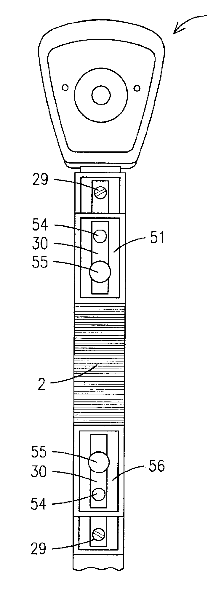
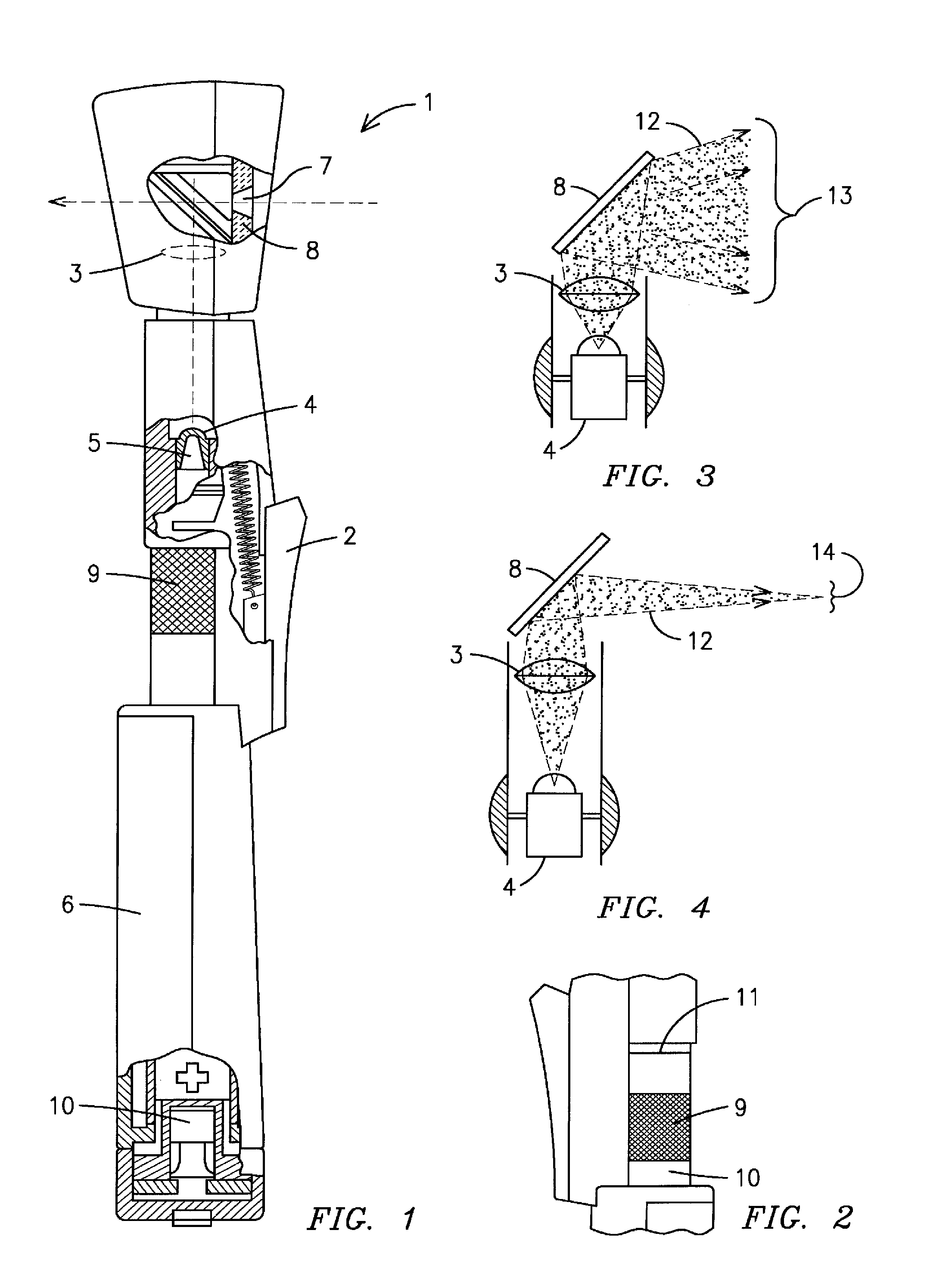
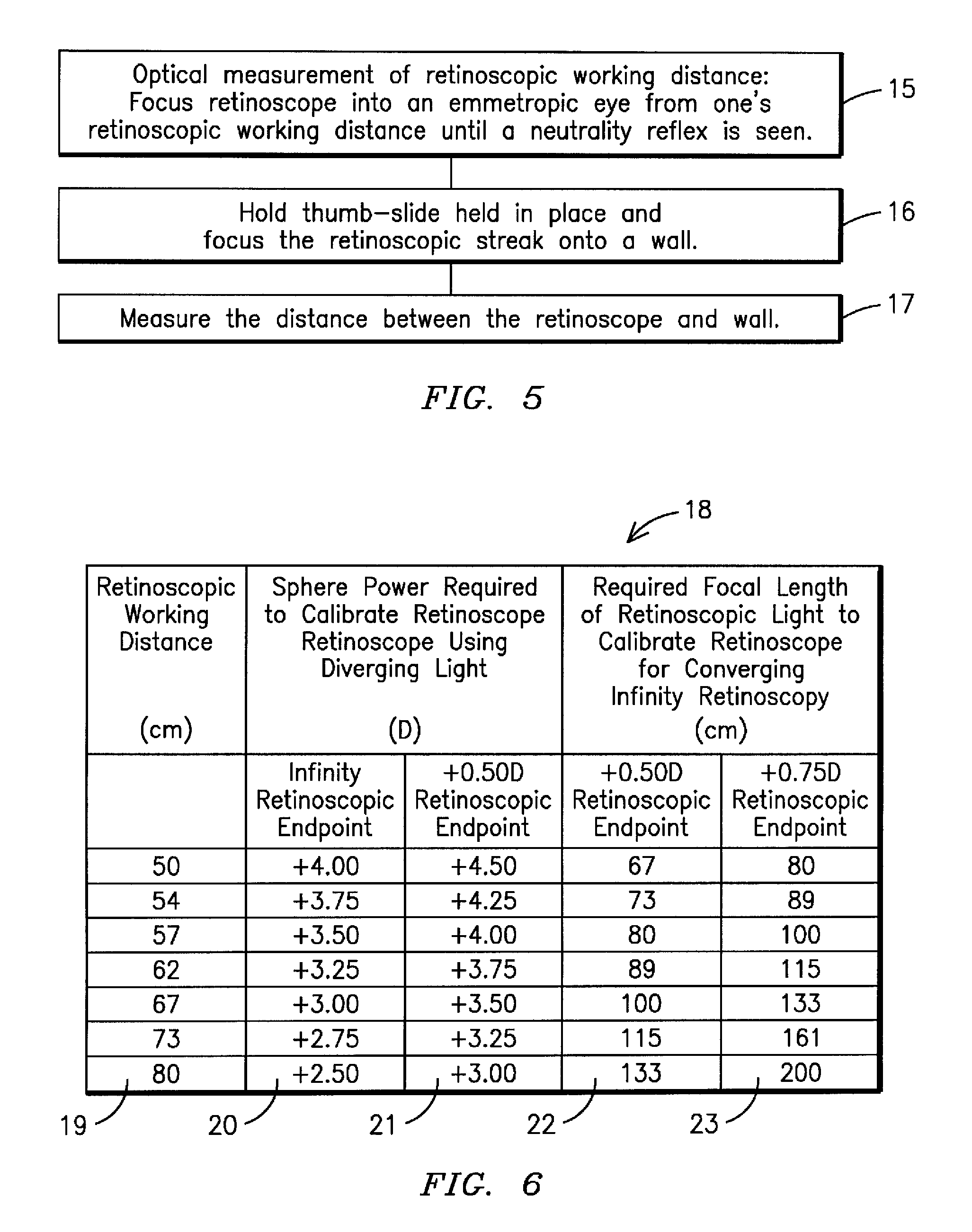
 1. retinoscope 2.thumb-slide 3. condensing lens 4. lamp 5. filament 6. handle of retinoscope 7. hole in mirror 8. mirror 9. knurl on power capsule10. power capsule11. calibration line on power capsule12. retinoscopic light rays13. diverging pattern14. converging pattern15. optical measurement of retinoscopic working distance:16. hold thumb-slide in place and focus retinoscope onto wall.17. measure distance between retinoscope and wall18. calibration chart19. retinoscopic working distance (cm)20. calibration sphere required for calibrated infinity endpoint usingdiverging light rays21. calibration sphere required for calibrated +0.50 D endpoint usingdiverging light rays22.required focal length of retinoscopic light for +0.50 D endpoint usingconverging light rays23. required focal length of retinoscopic light for +0.75 D endpoint usingconverging light rays24.plate25.+0.50 D converging plate26. front surface of calibration plate27. rear surface of calibration plate28.alignment line29.a...


PUM


Abstract

A device for calibrating retinoscopes for diverging and / or converging streak and spot retinoscopy and a method for calibrating retinoscopes to produce a given convergence or divergence of light emitted from the retinoscope from a fixed retinoscopic working distance to produce a predetermined pupillary reflex endpoint at neutralization of a refractive error, thereby resulting in a more accurate corrective eye prescriptions and evaluation of the visual system.

Description

CROSS REFERENCE TO RELATED APPLICATION[0001]This is a continuation-in-part application of Ser. No. 12 / 764,216 filed on Apr. 21, 2010. The patent application identified above is incorporated herein by reference in its entirety to provide continuity of disclosure.BACKGROUND OF THE INVENTION[0002]This invention relates to devices and methods for measuring and determining the refractive error in eyes and more particularly, a device for calibrating retinoscopes for diverging and / or converging retinoscopy and a method for calibrating retinoscopes using the device.[0003]Retinoscopy is a technique used by practitioners, such as optometrists and ophthalmologists, to obtain an objective measurement of the refractive error of a patient's eyes in order to determine the patient's prescription for spectacles and / or contacts lenses. Varying retinoscopic measurements are frequently obtained with the current retinoscopes. These retinoscopic errors are due the distance between the condensing lens wit...

Claims


Application Information

Patent Timeline
Patent Type & Authority Patents(United States)
IPC IPC(8): A61B3/10
CPCA61B3/103A61B3/1208
Inventor SIMS, CLINTON N.
Owner SIMS CLINTON N
Why Eureka
Try Eureka