
Universal cell carrier

a cell carrier and universal technology, applied in the field of universal cell carriers, can solve the problems of insufficient ablation lesions and constant movement of the heart, and achieve the effect of reducing the number of unique parts

Inactive Publication Date: 2012-09-25
ST JUDE MEDICAL ATRIAL FIBRILLATION DIV
View PDF26 Cites 0 Cited by
  • Summary
  • Abstract
  • Description
  • Claims
  • Application Information

AI Technical Summary

Benefits of technology

[0008]It is desirable to be able to reduce the number of unique parts that need to be manufactured to produce cells of varying heights in an ablation device.
[0009]Thus, there remains a need for a universal cell carrier that may be easily and inexpensively modified to provide for varying heights for mid cells and / or to provide the features required in distal or proximal cell carriers.
[0010]A carrier for an ablation element is provided. The carrier includes a plurality of walls defining a receiving portion configured to receive at least a portion of an ablation element. A plurality of connection formations are disposed on an exterior surface of least one of the plurality of walls. Each of the plurality of connection formations is disposed at a different vertical position of the carrier. A top may also be provided that is configured for connection to the carrier. The top may include a plurality of legs extending inwardly, and the legs may be configured for connection to one of the plurality of connection formations. The top may, therefore, be connected at various connection formations disposed on the carrier to provide a variable space between the carrier and the top.

Problems solved by technology

One difficulty in obtaining an adequate ablation lesion is the constant movement of the heart, especially when there is an erratic or irregular heart beat.
Another difficulty in obtaining an adequate ablation lesion is retaining uniform contact with the cardiac tissue across the entire length of the ablation element surface.
Without sufficiently continuous and uniform contact, the associated ablation lesions may not be adequate.

Method used


Image

  • Universal cell carrier
  • Universal cell carrier
  • Universal cell carrier

Examples


Embodiment Construction

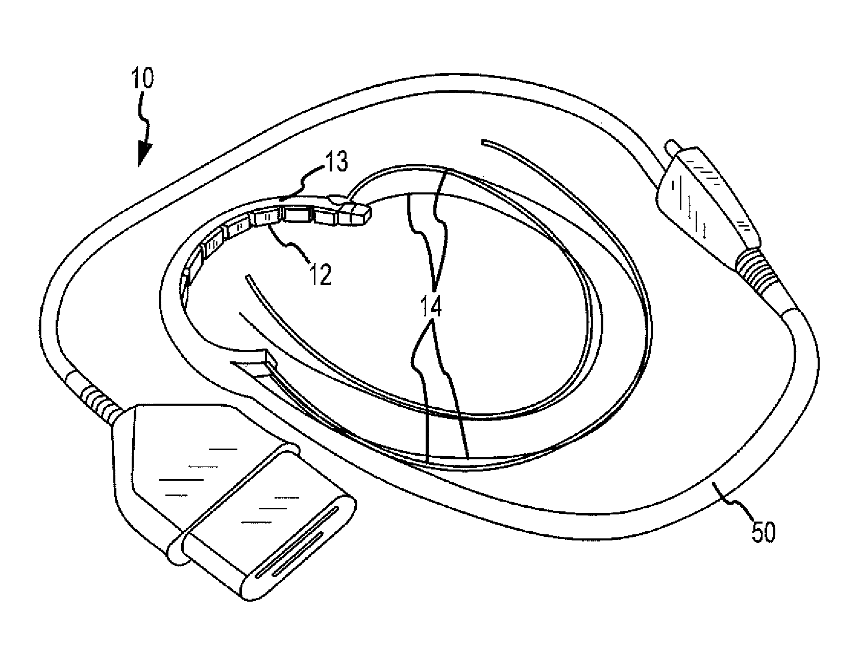
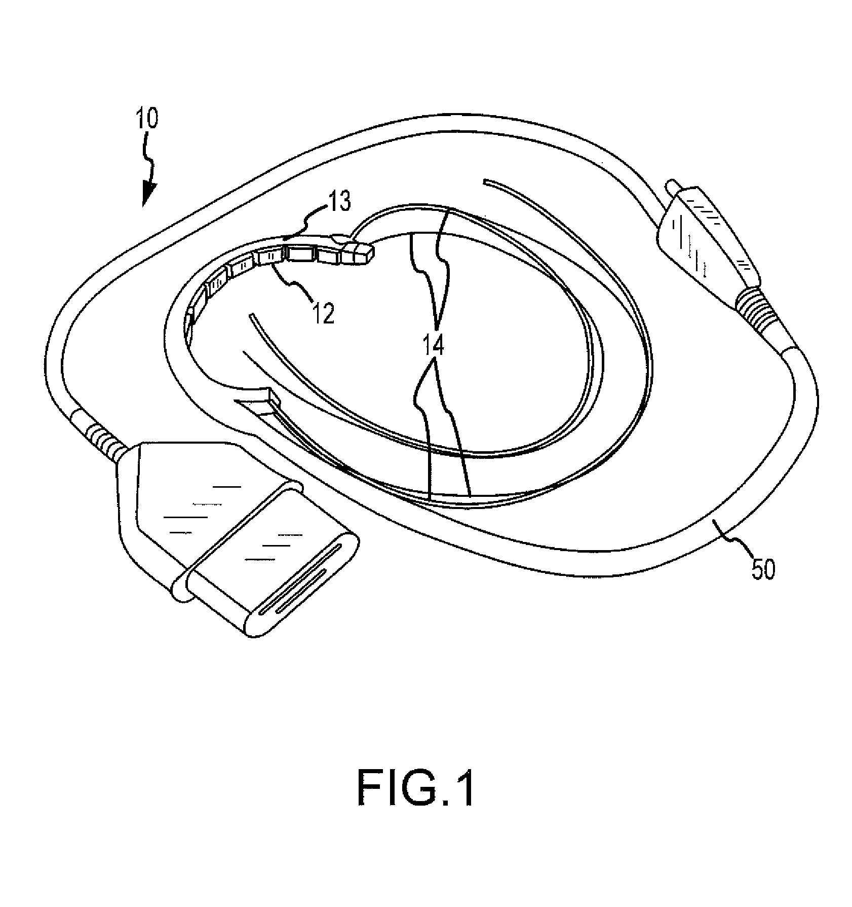
[0020]Referring now to FIG. 1, an epicardial ablation device 10 is illustrated. Device 10 may comprise a series of cells 12 at a first end. Each cell 12 may be movable within a lumen in a body 13. The body 13 may form two suction channels to adhere device 10 to the target tissue. The body 13 may have a curved form and may be made of a flexible material to allow body 13 to form a substantially closed loop. However, it is understood by those of ordinary skill in the art that body 13 may be shaped in any other manner and remain within the spirit and scope of the invention. Body 13 may be connected (e.g., locked) to itself to encircle at least a portion of the heart (e.g., the pulmonary veins) for creating a continuous lesion. Although the device has been described in connection with creating a continuous lesion around the pulmonary veins, it is understood by those of ordinary skill in the art that the device may also be used for creating other lesions beneficial in treating electrophys...


PUM


Abstract

A carrier for an ablation element is provided. The carrier includes a plurality of walls defining a receiving portion configured to receive at least a portion of an ablation element. A plurality of connection formations are disposed on an exterior surface of least one of the plurality of walls. Each of the plurality of connection formations is disposed at a different vertical position of the carrier. A device for epicardial ablation is also provided. The device includes a plurality of carriers disposed adjacent to each other. Each carrier includes a plurality of walls defining a receiving portion configured to receive at least a portion of an ablation element. A plurality of connection formations are disposed on an exterior surface of at least one of the plurality of walls of each carrier. Each of the plurality of connection formations is disposed at a different vertical position of a carrier.

Description

BACKGROUND OF THE INVENTION[0001]a. Field of the Invention[0002]The instant invention is directed toward a universal cell carrier, including a universal cell carrier for housing an ablation element, such as for use in an epicardial ablation device.[0003]b. Background Art[0004]In a normal heart, contraction and relaxation of the heart muscle (myocardium) takes place in an organized fashion as electrochemical signals pass sequentially through the myocardium from the sinoatrial (SA) node located in the right atrium to the atrialventricular (AV) node and then along a well defined route which includes the His-Purkinje system into the left and right ventricles. Atrial fibrillation results from disorganized electrical activity in the heart muscle, or myocardium. An increasingly common medical procedure for the treatment of certain types of cardiac arrhythmia and atrial arrhythmia involves the ablation of tissue in the heart to cut off the path for stray or improper electrical signals.[0005...

Claims


Application Information

Patent Timeline
Patent Type & Authority Patents(United States)
IPC IPC(8): A61B18/14
CPCA61B18/14A61B19/26A61B2018/00363A61B2018/00375A61N7/022A61B90/50
Inventor RADIN, ANDREW M.EBY, THOMAS B.BOUDTCHENKA, VERA S.TENG, JENNIFERGOETZ, JOHN P.CROWE, JOHN E.
Owner ST JUDE MEDICAL ATRIAL FIBRILLATION DIV
Learn More