Three element coaxial vaso-occlusive device

a vaso-occlusive device and coaxial technology, applied in the field ofvasoocclusive devices, can solve the problems of decreasing and achieve the effects of reducing the contact area, reducing the aggregate friction, and reducing the resistance to device manipulation

Active Publication Date: 2012-09-25
MICROVENTION INC
View PDF62 Cites 37 Cited by
  • Summary
  • Abstract
  • Description
  • Claims
  • Application Information

AI Technical Summary

Benefits of technology

[0012]In a preferred embodiment of the invention, the inner element is in the form of a helical coil made of a biocompatible, radiopaque metal, and the intermediate element is a conformal coating or layer on the inner element, the conformal coating or layer being made of a soft polymeric material that is preferably an expansile polymer. Advantageously, the polymeric hydrogel is an environmentally-responsive hydrogel that expands upon exposure to the physiological environment, for example, of the blood stream. The polymer may advantageously be bio-absorbable or biodegradable. Also in the preferred embodiment, the outer element is a helical “over-coil” that is loosely wound (“open-wound”) over the intermediate element, except at proximal and distal end sections, where it is tightly wound (“close-wound”). The close-wound proximal and distal end sections support the inner element, protecting it from damage during deployment and any necessary repositioning, while also securely binding the intermediate element to the inner element at the proximal and distal ends of the device and restraining the hydrogel of the intermediate element from expanding at the respective ends of the device. The open-wound section between the proximal and distal end sections creates a single, continuous helical opening through which the intermediate element expands. The helical configuration of the opening forces the expanded polymeric intermediate element to assume the configuration of a chain of arcuate segments protruding radially outwardly between the coils of the over-coil, rather than that of a continuous polymeric layer having a continuous, uninterrupted exterior surface. Because each of the arcuate segments contacts the interior surface of a microcatheter (e.g., during deployment) primarily at or near a tangential contact point, the total contact area of the intermediate element is reduced as compared to a continuous axial polymeric element. This reduced contact area correspondingly reduces the aggregate friction between the polymeric layer and the microcatheter, thereby decreasing the resistance to manipulation of the device. The open-wound section also creates hinge points between the arcuate segments of the polymeric intermediate element, thereby increasing the overall flexibility of the device.
[0013]It has been confirmed experimentally that the reduced friction and increased flexibility afforded by the outer element, and by the interaction between the outer and intermediate elements, enhances the both the pushability and trackability of a device made in accordance with the present invention, as compared, for example, with prior art microcoil devices having expansile polymeric coatings or elements on or along their exterior surfaces.
[0014]The invention thus provides a microcoil vaso-occlusive device with an expansile element that allows the device to embolize very efficiently a wide variety of vascular abnormalities, e.g., aneurysms of a wide variety of shapes, sizes, and locations, and yet that exhibits enhanced pushability and trackability as compared to the prior art.

Problems solved by technology

This reduced contact area correspondingly reduces the aggregate friction between the polymeric layer and the microcatheter, thereby decreasing the resistance to manipulation of the device.

Method used


Image

  • Three element coaxial vaso-occlusive device
  • Three element coaxial vaso-occlusive device
  • Three element coaxial vaso-occlusive device

Examples


Embodiment Construction

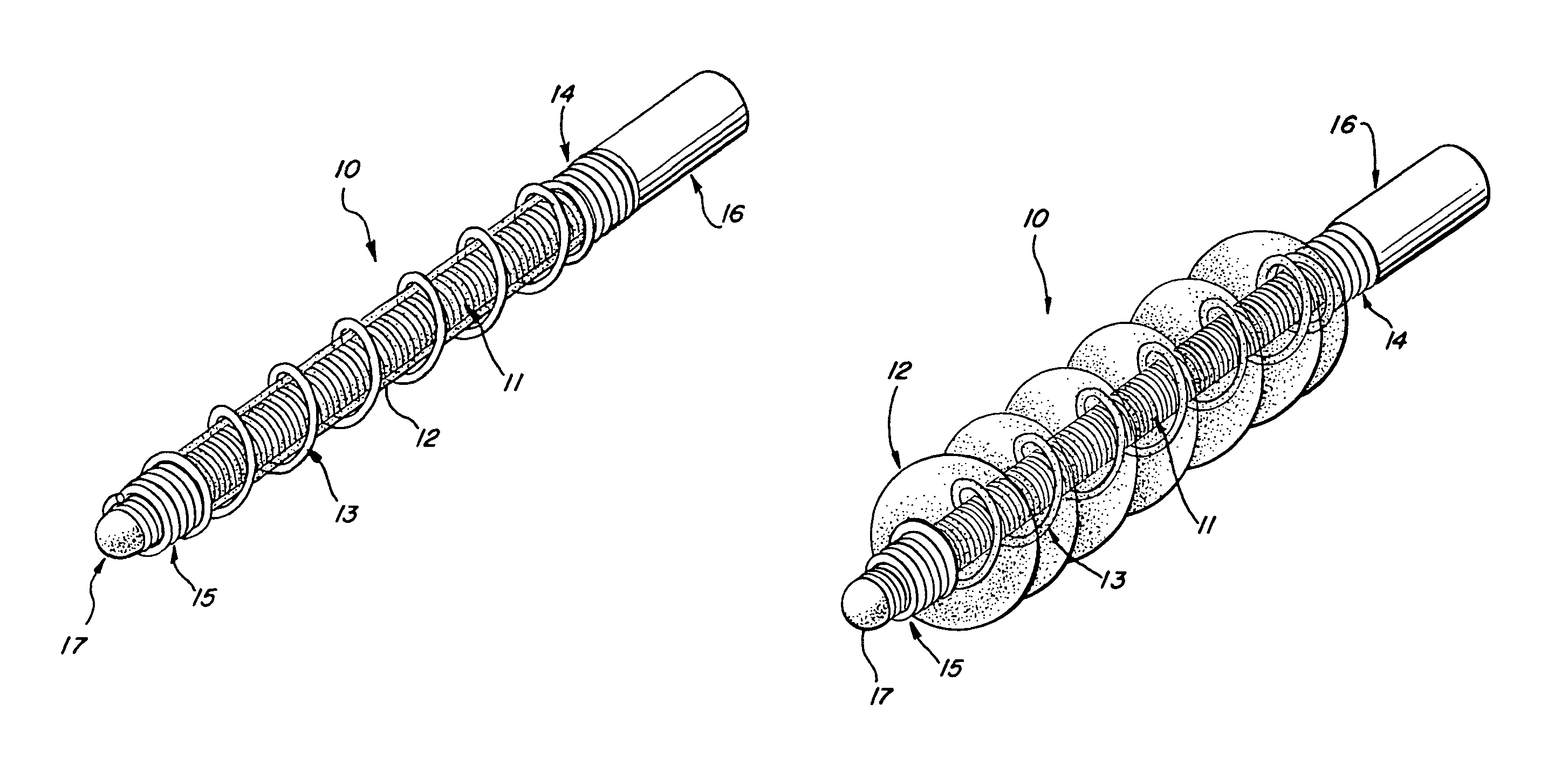
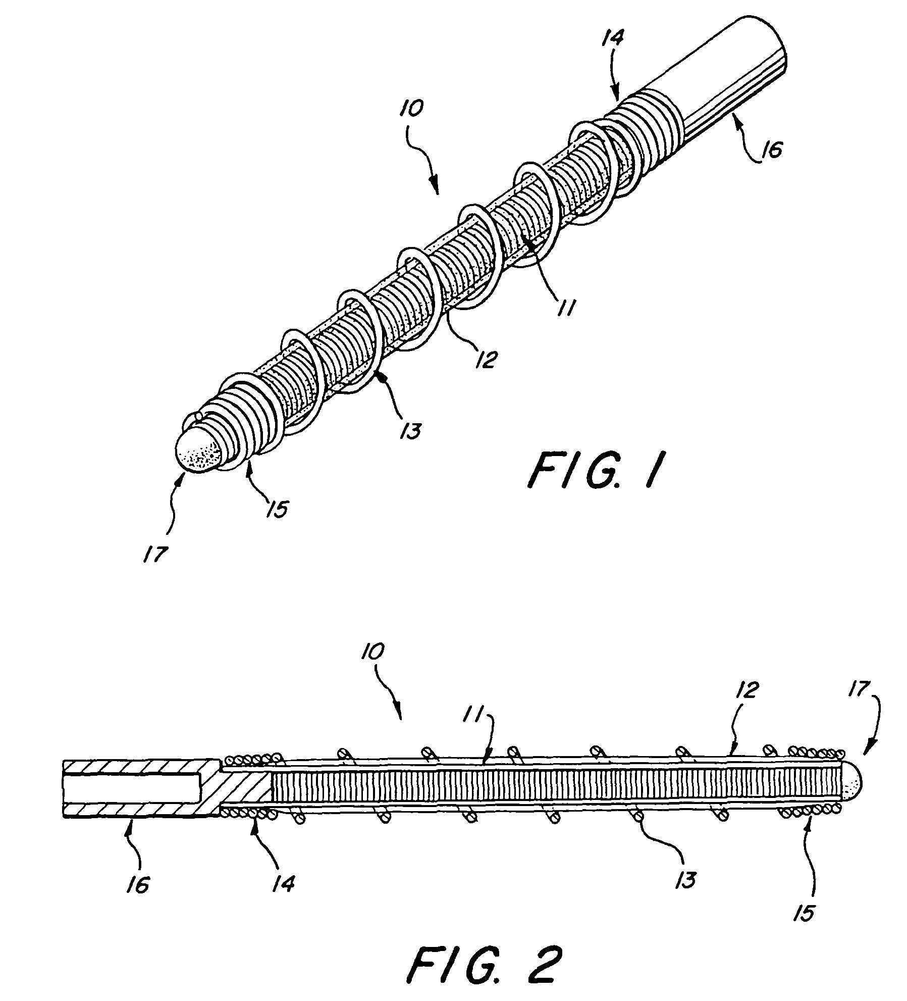
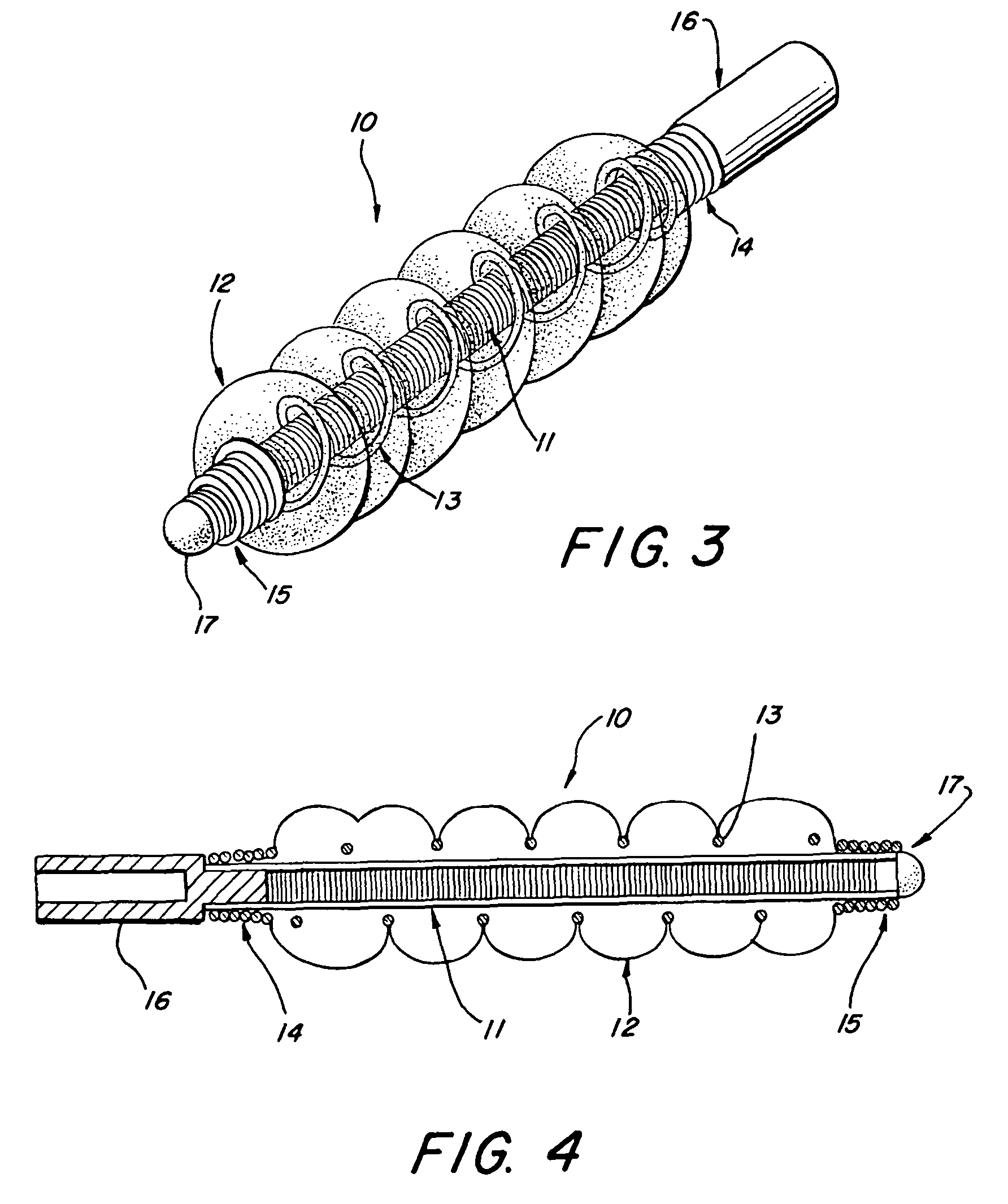
[0020]Referring to FIGS. 1-4, a vaso-occlusive device 10, in accordance with a preferred embodiment of the invention, comprises three elongate, coaxial elements: an inner core element 11, a non-metallic intermediate element 12, and a non-expansile outer element 13 that covers at least a portion of the intermediate element. The intermediate element 12 is in intimate contact with both the inner element 11 and the outer element 13.

[0021]The inner element 11 is formed of a flexible, elongate filament or wire that is preferably made of a material that allows visualization under various medical imaging means, such as X-ray, MRI, or ultrasound. Preferably, the inner element 11 is formed from a length of wire made of any of various biocompatible, radiopaque metals, such as platinum, tantalum, tungsten, gold, titanium, nitinol, stainless steel, Elgiloy (cobalt-chromium-nickel), or other suitable alloys known in the art. Alternatively, it can be made from or include non-metallic materials, su...


PUM


Abstract

A vaso-occlusive device includes inner, intermediate, and outer elements arranged coaxially. The inner element is a filamentous element, preferably a microcoil. The intermediate element is made of a non-metallic material, preferably an expansile polymer. The outer element is substantially non-expansile and defines at least one gap or opening through which the intermediate element is exposed. In a preferred embodiment, when the intermediate element is expanded, it protrudes through the at least one gap or opening in the outer element and assumes a configuration with an undulating, convexly-curved outer surface defining a chain of arcuate segments, each having a diameter significantly greater than the diameter of the outer element. The expanded configuration of the intermediate element minimizes friction when the device is deployed through a microcatheter, thereby reducing the likelihood of buckling while maintaining excellent flexibility. The result is a device with enhanced pushability and trackability when deployed through a microcatheter.

Description

ROSS-REFERENCE TO RELATED APPLICATION[0001]This application claims the benefit, under 35 U.S.C. Section 119(e), of co-pending provisional application No. 60 / 400,013, filed Jul. 31, 2002, the disclosure of which is incorporated herein by reference.FEDERALLY-SPONSORED RESEARCH OR DEVELOPMENT[0002]Not ApplicableBACKGROUND[0003]This invention relates to vaso-occlusive devices, such as vaso-occlusive coils and the like, for the embolization of vascular aneurysms and similar vascular abnormalities. Specifically, the invention is an improvement over existing two layer or two element coaxial vaso-occlusive devices, particularly those having a polymer coating or covering. In particular, the present invention is a three layer or three element coaxial vaso-occlusive device that provides improved durability, pushability, and trackability inside a microcatheter. The characteristic termed “trackability” relates to the ease of advancing one interventional device within or over another, and it is r...

Claims


Application Information

Patent Timeline
Patent Type & Authority Patents(United States)
IPC IPC(8): A61M29/04A61B17/00A61B17/12G06K9/00
CPCA61B17/12022A61B17/12113A61B17/12145A61B17/1215A61B17/1219A61B17/12177A61B2017/1205A61B2017/00004A61B2017/0084A61B2017/00867
Inventor MARTINEZ, GEORGE
Owner MICROVENTION INC
Why Eureka
Try Eureka