Apparatus and method for filter cleaning by ultrasound, backwashing and filter movement during the filtration of biological samples

a technology of filter movement and ultrasound, applied in the field of apparatus and methods for the separation of a therapeutic cellular fraction from a fluid sample, can solve the problems of reducing the cell surface, and achieve the effects of increasing the potential surface area, reducing the potential for solid matter, and increasing the filtration ra

Inactive Publication Date: 2012-09-25
SMITH & NEPHEW INC
View PDF115 Cites 93 Cited by
  • Summary
  • Abstract
  • Description
  • Claims
  • Application Information

AI Technical Summary

Benefits of technology

[0011]The transmission of an acoustic standing wave through the fluids within the filtration unit results in the agitation of the fluids, either continuously or in a pulsed manner, during the separation process. A particular advantage of this agitation is that is minimises the fouling and clogging of the filter.
[0077]The system can be operated manually. However, in order to improve the overall efficiency and accuracy of the separation process, particularly when the apparatus is used in an operating room situation by medical staff, the apparatus is advantageously automated. A Programmable Logic Controller (PLC) can be programmed to switch a vacuum pump and a backwashing pump on and off in cyclic rotation in a timed sequence. The vacuum pump draws the fluid sample downwards through the filter under negative pressure. The backwashing pump forces washing fluid upwards through the filter.

Problems solved by technology

Such passage through the pore is achievable by the deformation of the cell, but during the passage the cells may be exposed to undesirable stresses, such as shear stress, which may have deleterious effects on the cell.

Method used


Image

  • Apparatus and method for filter cleaning by ultrasound, backwashing and filter movement during the filtration of biological samples
  • Apparatus and method for filter cleaning by ultrasound, backwashing and filter movement during the filtration of biological samples
  • Apparatus and method for filter cleaning by ultrasound, backwashing and filter movement during the filtration of biological samples

Examples


Embodiment Construction

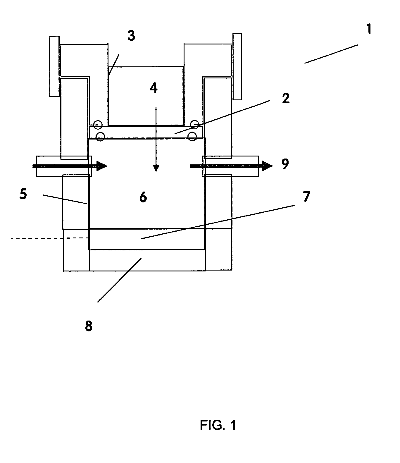
[0106]FIG. 1: A schematic showing the general operating principle of the apparatus of the invention in which the following reference numerals refer:[0107]1. Filtration unit[0108]2. Porous filter[0109]3. Upper (pre-filtration) chamber for receiving fluid sample.[0110]4. Fluid sample[0111]5. Lower (post-filtration) chamber for receiving back-flushing fluid.[0112]6. Fluid provided in the post-filtration chamber[0113]7. Resonating substrate[0114]8. Acoustic wave generating element[0115]9. Vacuum draw (optional)

[0116]The porous filter 2 separates a filtration unit 1 into two chambers; an upper (pre-filtration) chamber 3 into which a fluid sample 4 requiring cell separation is introduced and a lower (post-filtration) chamber 5 into which a fluid 6 capable of transmitting an acoustic standing wave is introduced. An acoustic element 8 is coupled to a substrate 7•which is located within and at the bottom of the lower chamber and which resonates in response to the acoustic generating element ...


PUM

PropertyMeasurementUnit
frequencyaaaaaaaaaa
frequencyaaaaaaaaaa
pore diameteraaaaaaaaaa

Abstract

The present application is directed to the separation of—a solid fraction from a fluid sample particularly a therapeutic cellular fraction from a biological sample such as a bone marrow sample by a porous filter (2) which separates a filtration unit (1) into an upper pre-filtration chamber (3) into which a fluid sample (4) requiring cell separation is introduced and a lower post-filtration chamber (5) into which a fluid (6) capable of transmitting an acoustic standing wave is introduced. An acoustic element (8) is coupled to a substrate (7) which is located within and at the bottom of the lower chamber (5) and which resonates in response to the acoustic generating element (8) and generates a standing wave through the two fluid phases and the filter to agitate the sample (4). Simultaneously, a cyclic process of vacuum draw (9). causes movement of the sample (4) downwards through the filter (2). Vacuum pressure, fluid flow rate and frequency of vibration are controlled from a remote unit housing appropriate pumps and valves.

Description

RELATED APPLICATIONS[0001]This application is the U.S. national phase of International Application No. PCT / GB2008 / 000704 filed on 29 Feb. 2008 published in English on 12 Dec. 2008 as International Publication No. WO 2008 / 107652 A1, which application claims the priority to UK provisional application No. 0704180.9 filed on 2 Mar. 2007, UK provisional application No. 0722448.8 filed on 15 Nov. 2007 and UK provisional application 0801901.0 filed on 1 Feb. 2008, all of which are herein incorporated in their entirety.FIELD OF THE INVENTION[0002]The present invention concerns the separation of a solid fraction from a fluid sample. In particular the invention relates to apparatus and methods for the separation of a therapeutic cellular fraction from a biological sample, such as a bone marrow sample.BACKGROUND OF THE INVENTION[0003]Progenitor cells have multi-lineage potential when differentiated and therefore potentially lend themselves to a diverse range of therapeutic treatments. It is co...

Claims


Application Information

Patent Timeline
Patent Type & Authority Patents(United States)
IPC IPC(8): C02F1/34
CPCB01L3/50255B01D29/62C02F1/34C12M47/02B01L2400/0436B01L2400/0487C02F2209/005C12M3/06B01D29/86B01D29/66B01L3/00
Inventor CURRAN, STEPHEN
Owner SMITH & NEPHEW INC
Why Eureka
Try Eureka