Automatic punching detection equipment for shaft tube products

A technology for testing equipment and products, applied in metal processing equipment, perforating tools, chemical instruments and methods, etc., can solve problems such as low detection efficiency, achieve the effect of saving labor costs, improving overall efficiency and accuracy

Pending Publication Date: 2022-04-01
奥特凯姆(中国)汽车部件有限公司
View PDF0 Cites 0 Cited by
  • Summary
  • Abstract
  • Description
  • Claims
  • Application Information

AI Technical Summary

Problems solved by technology

[0003] In order to solve the above problems, the present invention proposes an automatic punching detection equipment for shaft tube products, which solves the problem of low production and detection efficiency of existing shaft tube products

Method used


Image

  • Automatic punching detection equipment for shaft tube products
  • Automatic punching detection equipment for shaft tube products
  • Automatic punching detection equipment for shaft tube products

Examples


Embodiment Construction

[0023] The technical solutions protected by the present invention will be specifically described below in conjunction with the accompanying drawings.

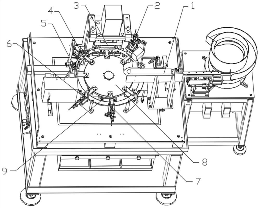
[0024] Such as figure 1 As shown, an automatic punching detection equipment for shaft tube products includes: an indexing plate 8, where a feeding mechanism 1, a positive and negative detection mechanism 2, a punching mechanism 3, a blowing Gas mechanism 4, detection mechanism 5, first blanking mechanism 6, second blanking mechanism 7, a circle of baffles 10 are arranged on the periphery of said indexing plate 8, said baffles 10 are arranged on the punching mechanism 3, the second The first feeding mechanism 6 and the second feeding mechanism 7 are respectively provided with a through hole, the index plate 8 rotates, and the baffle plate 10 does not rotate. When the product arrives at these several mechanisms with the jig, the product falls into the corresponding Station;

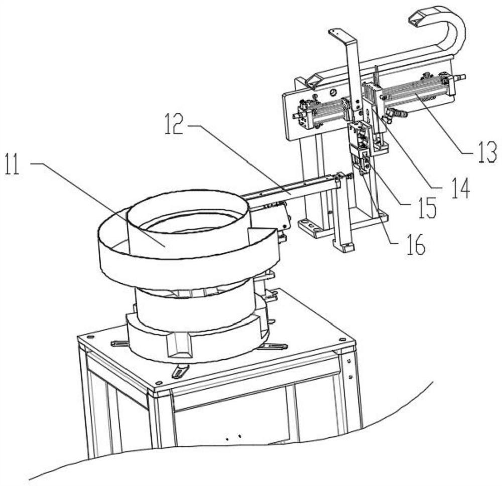
[0025] Among them, the feeding mechanism 1 is used t...


PUM


Abstract

The invention provides shaft tube type product automatic punching detection equipment which comprises an index plate, a feeding mechanism, a forward and reverse detection mechanism, a punching mechanism, a blowing mechanism, a detection mechanism, a first discharging mechanism and a second discharging mechanism are sequentially arranged on the index plate, and a circle of baffle is arranged on the periphery of the index plate. The baffle is provided with a through hole in the punching mechanism, the first discharging mechanism and the second discharging mechanism respectively. By means of the mode, the problem that the production and detection efficiency of existing shaft tube products is low is solved.

Description

technical field [0001] The invention relates to the field of automatic production, in particular to an automatic punching detection device for shaft tube products. Background technique [0002] The shaft tube product is a shaft product with a middle hole, which is widely used in many fields such as auto parts and aerospace. When the existing shaft tube products are processed, the middle hole needs to be stamped and produced, and one person needs to manually discharge and take out the material on one piece of equipment. In normal production, one person can only operate one piece of equipment. Manual production requires a long time to take and unload each part. Not only is the efficiency low, but manual unloading is prone to the problem of inaccurate unloading positions. After the punching is completed, the product needs to be manually inspected, and the inspection efficiency is low, resulting in a long production cycle. Contents of the invention [0003] In order to solve...

Claims


Application Information

Patent Timeline
IPC IPC(8): B21D28/34B21D28/28B21D28/04B21D43/14B21D43/02B21C51/00B07C5/02B07C5/34B07C5/36B08B5/02
Inventor 崔虎
Owner 奥特凯姆(中国)汽车部件有限公司
Why Eureka
Try Eureka