Touch position detection method for touch control device

a technology of touch control device and position detection, which is applied in the direction of mechanical pattern conversion, instruments, computing, etc., can solve the problems of not teaching to determine if, insufficient knowledge of techniques, and discontinuous trace of stylus writing

Active Publication Date: 2012-09-25
TRENDON TOUCH TECHNOLOGY CORPORATION
View PDF11 Cites 34 Cited by
  • Summary
  • Abstract
  • Description
  • Claims
  • Application Information

AI Technical Summary

Benefits of technology

[0012]The technical solution taken in the present invention allows a conventional resistive type touch control device to not only detect the coordinates of multiple touch points, but also to switch to different operation modes corresponding to different situations of the detection of coordinates to be thereby capable to detect coordinates for various types of touch, including a single-point touch, a multiple-point touch, and a continuous trace constituting an input of stylus writing. Thus, the method of the present invention can both be used to detect coordinates of a single-point touch and a multiple-point touch and be suitable for detection of coordinates of touched sites in a stylus writing application.

Problems solved by technology

When the known techniques are employed to detect the continuous trace of stylus writing input, the detected result is a discontinuous trace of stylus writing.
Further, the prior arts do not teach to determine if the touch operation applied to a touch panel is single-point touch, multiple-point touch, or continuous trace.
Thus, such known techniques are still insufficient to meet the practical requirements for applications of the related products.

Method used


Image

  • Touch position detection method for touch control device
  • Touch position detection method for touch control device
  • Touch position detection method for touch control device

Examples


first embodiment

[0030]Referring to FIG. 4, which illustrates a flow chart of a detection method carried out in accordance with the present invention, after system initialization of the touch control device is completed (step 101), the microcontroller 4 initializes a preset scan detection mode to perform driving and scan detection respectively on the first conductive layer 10 and the second conductive layer 20 (step 102).

[0031]The preset scan detection mode includes a first operation mode and a second operation mode. In practice, one of these two operation modes can be selected as the preset scan detection mode.

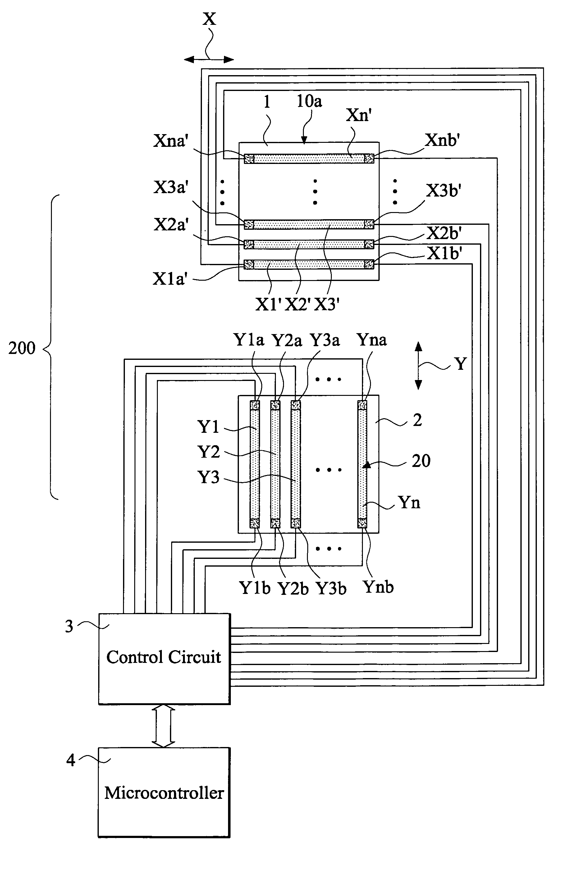
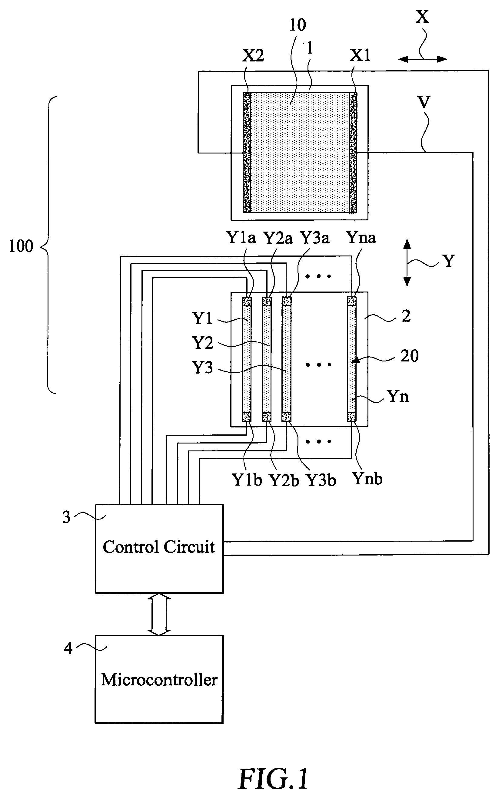
[0032]When the first operation mode is selected as the preset scan detection mode, the following steps are carried out: The control circuit 3 applies a drive voltage to the first conductive layer 10 and carries out scan detection on at least one end of the first end Y1a, Y2a, Y3a, . . . , Yna and the second end Y1b, Y2b, Y3b, . . . , Ynb of each elongate conductive strip Y1, Y2, Y3, . . . , Y...

second embodiment

[0038]Referring to FIG. 5, which illustrates a flow chart of an operation carried out in accordance with the present invention, in the instant embodiment, after system initialization of the touch control device is completed (step 201), the microcontroller 4 initializes a preset scan detection mode to perform driving and scan detection respectively on the first conductive layer 10 and the second conductive layer 20 (step 202).

[0039]The preset scan detection mode includes a first operation mode and a second operation mode. In practice, one of these two operation modes can be selected as the preset scan detection mode. The detailed operation flows associated with the first and second operation modes are identical to those of the first embodiment.

[0040]When a user touches the touch panel, the microcontroller 4 determines the type of the touch operation (step 203). If it is determined that the type of touch operation applied to the touch panel is a multiple-point touch (step 204), the mi...


PUM


Abstract

Disclosed is a touch position detection method for a touch control device, which employs a preset scan detection mode to carry out driving and scan detection on first and second conductive layers through a control circuit. When touch on a touch panel is detected, the type of the touch is determined, which may include a single-point touch, a continuous trace, and a multiple-point touch, and first and second operation modes are selectively used to perform driving and scan detection on the first and second conductive layers of the touch panel to thereby detect coordinates of the touch points or the continuous trace.

Description

FIELD OF THE INVENTION[0001]The present invention relates to a touch position detection method, and in particular to a method that determines the type of touch of a touch panel to be either a single-point touch, a continuous trace, or a multiple-point touch and selectively employs a corresponding operation mode to perform driving and scanning on the touch panel for coordinates detection.BACKGROUND OF THE INVENTION[0002]A conventional touch panel includes a first substrate with a first conductive layer and a second substrate with a second conductive layer. The first and second substrates are spaced from each other by insulation spacers therebetween. When a user touches the touch panel, variation of voltage at the touched site is used for the calculation and determination of the position coordinates of the touched site by a microprocessor with known formulas.[0003]The first and second conductive layers can be of a continuous planar structure, or can alternatively be of a structure com...

Claims


Application Information

Patent Timeline
Patent Type & Authority Patents(United States)
IPC IPC(8): G09G5/00G06F3/045G06F3/044G06F3/041G06K11/06G08C21/00
CPCG06F3/0416G06F3/045G06F3/04162G06F3/04166
Inventor LIU, CHEN-YULIN, CHUN-CHI
Owner TRENDON TOUCH TECHNOLOGY CORPORATION
Why Eureka
Try Eureka