Slip gear structure and timepiece equipped with the same

a technology of gear structure and timepiece, which is applied in the direction of slip coupling, instruments, and loss of slip engagement, and can solve the problems of type of slip gear not suited to application to a portion where disassembly/assembly, etc., and achieves the effect of convenient handling

Inactive Publication Date: 2012-09-25
SEIKO INSTR INC
View PDF11 Cites 8 Cited by
  • Summary
  • Abstract
  • Description
  • Claims
  • Application Information

AI Technical Summary

Benefits of technology

[0009]It is an aspect of the present invention to provide a slip gear structure which is easy to handle at the time of dismantling / assembly and which does not easily suffer breakage even if dismantling / assembly is repeated, and a timepiece equipped with the same.

Problems solved by technology

However, this swaging structure not only requires a sufficient wall thickness for swaging, but involves generation of play when dismantling and assembly are repeated, resulting in the loss of slip engagement.
However, in this type of slip gear using an arm-like spring, there is no appropriate portion to be retained (grabbed) at the time of dismantling / assembly, so that there is a fear of breakage at the time of dismantling / assembly, which means, this type of slip gear is not suited for application to a portion where dismantling / assembly is conducted (e.g., where gears are arranged coaxially on both main surface sides of a support substrate such as a main plate.

Method used


Image

  • Slip gear structure and timepiece equipped with the same
  • Slip gear structure and timepiece equipped with the same
  • Slip gear structure and timepiece equipped with the same

Examples


Embodiment Construction

[0039]Preferred embodiments of the present invention will be described with reference to the attached drawings.

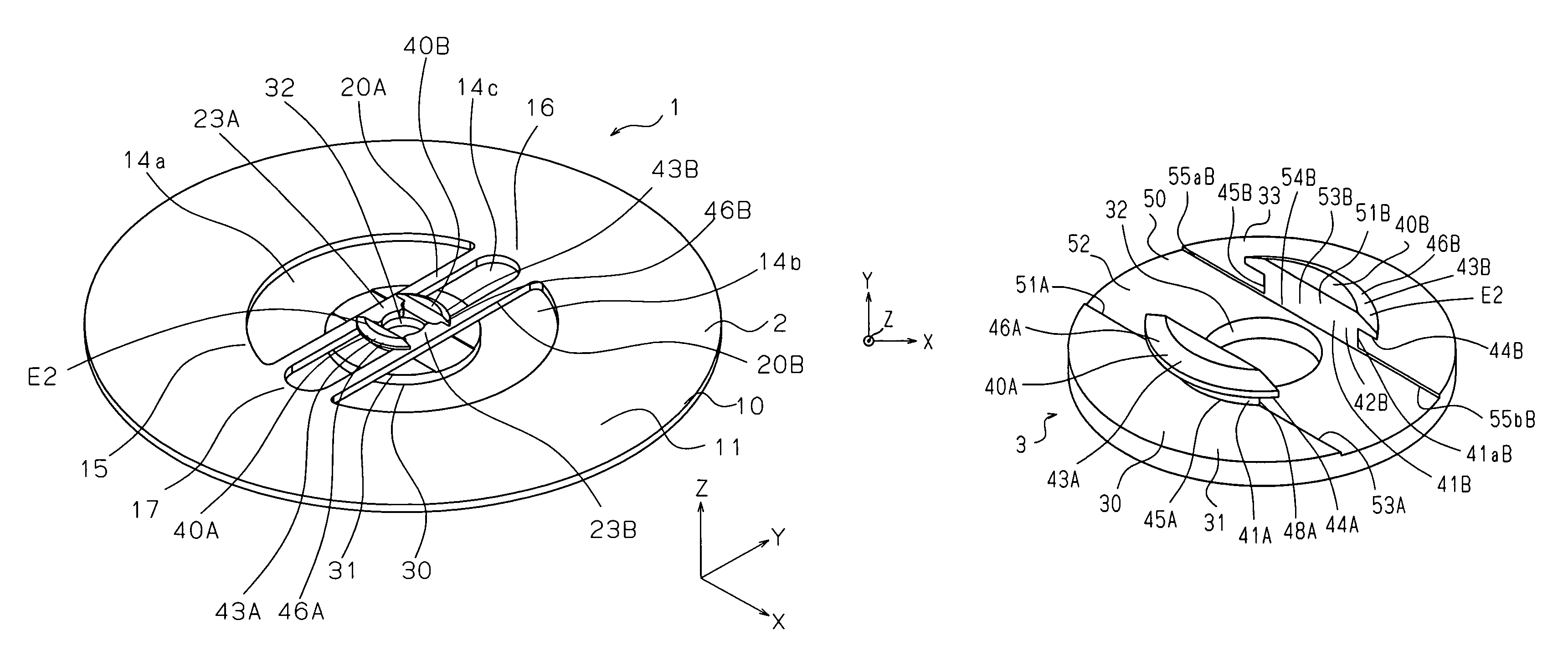
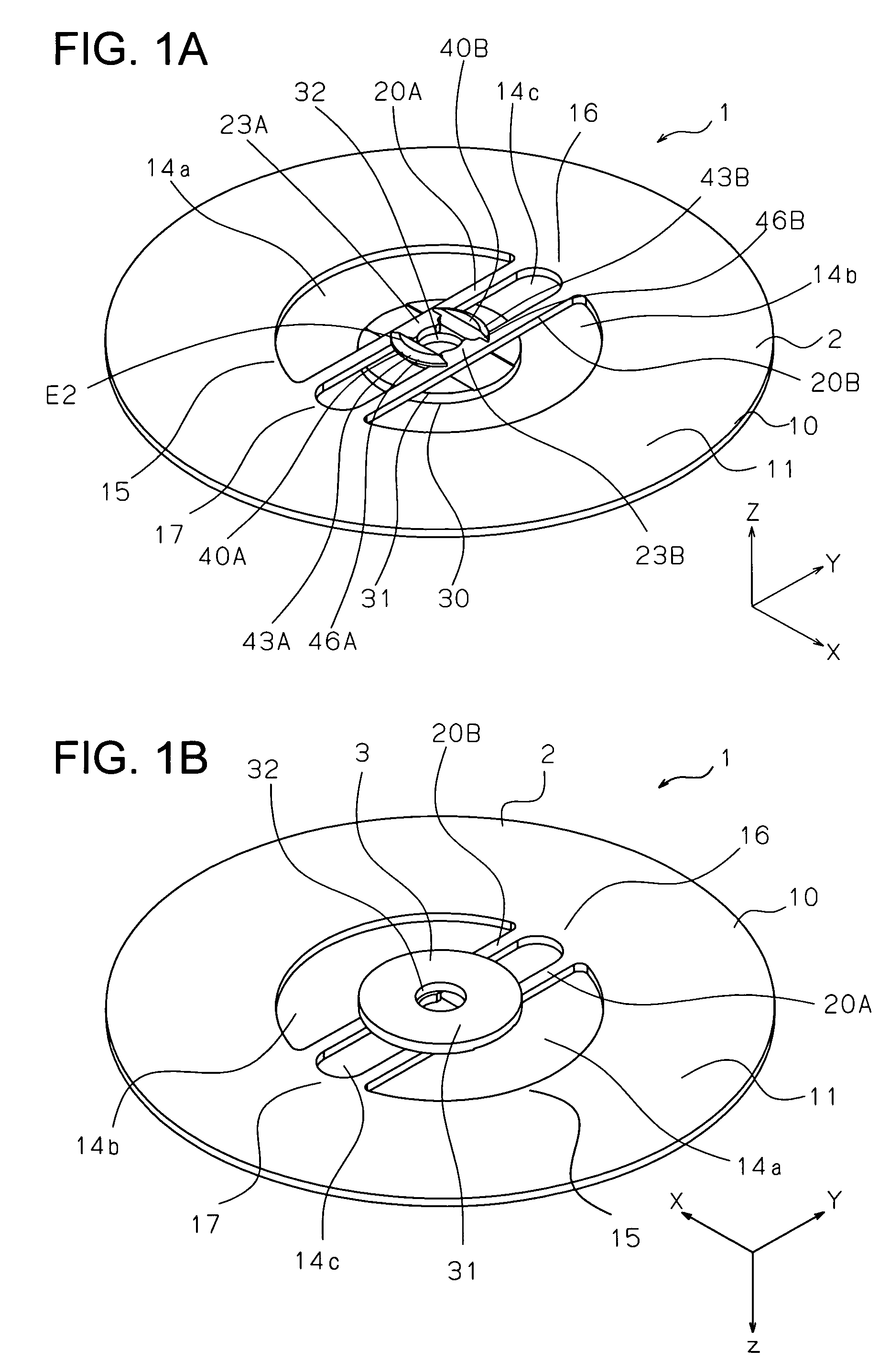
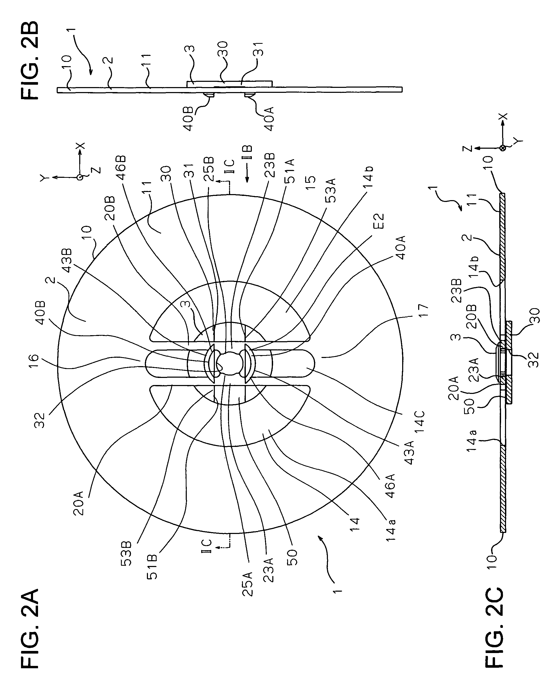
[0040]As shown in FIGS. 1A and 1B, FIGS. 2A, 2B, and 2C, and FIGS. 3A and 3B, a slip gear structure 1 according to a preferred embodiment of the present invention has a gear main body portion 2, and a support member or an auxiliary member 3 serving as a positioning member.

[0041]In a state in which it is slip-engaged with a shaft 4, the slip gear structure 1 assumes a form as shown in the plan sectional view of FIG. 5, and, in the state prior to the slip-engagement with the shaft 4, shown in FIGS. 1A through 3B, it assumes a form as shown in the plan sectional view of FIG. 4.

[0042]The gear main body portion 2 constituting the slip gear structure 1 has a form as shown in FIGS. 7A and 7B, and the support member or the auxiliary member 3 serving as the positioning member of the slip gear structure 1 has a form as shown in FIGS. 6A, 6B, 6C, 6D, and 6E.

[0043]The gear main body po...


PUM


Abstract

Disclosed is a slip gear structure which is easy to handle at the time of dismantling / assembly and which does not easily suffer breakage even if dismantling / assembly is repeated, and a timepiece equipped with the same. A slip gear structure for a timepiece includes: a gear main body portion in the form of an annular plate having in the outer periphery thereof tooth portions, there being provided spring portions extending across an inner opening; and a positioning member equipped with a small diameter plate-like portion having a central hole with which a shaft is rotatably fit-engaged and a pair of support wall portions arranged on both sides of the central hole and protruding from one surface. When the slip gear structure is in a non-fit-engaged state with respect to the shaft, the spring portions of the gear main body are elastically pressed against side edge portions of the support wall portions, with central spring portions thereof situated between the side edge portions protruding into the central hole; and when the slip gear structure is in a fit-engaged state with respect to the shaft at the central hole, the central spring portions of the spring portions of the gear main body portion are elastically pressed against the shaft for slip engagement with the shaft.

Description

BACKGROUND OF THE INVENTION[0001]1. Field of the Invention[0002]The present invention relates to a slip gear structure and a timepiece equipped with the same.[0003]2. Description of the Related Art[0004]There has conventionally been known a slip gear structure in which a shaft and a gear main body are slip-engaged with each other so that they may rotate integrally during normal operation and that when the load applied between the shaft and the gear increases to a degree not less than a certain level, slippage may be generated between the shaft and the gear; it is applied, for example, to a winding mark wheel of a power reserve mechanism (winding mark mechanism), and a wheel related to time correction, etc. of a chronograph timepiece or the like.[0005]In such a slip gear, there is typically adopted a swaging structure called cannon pinion crushing (See, for example, JP-A-2000-98056).[0006]However, this swaging structure not only requires a sufficient wall thickness for swaging, but i...

Claims


Application Information

Patent Timeline
Patent Type & Authority Patents(United States)
IPC IPC(8): G04B19/02
CPCF16D7/021G04B11/003
Inventor ONO, TAMOTSU
Owner SEIKO INSTR INC
Why Eureka
Try Eureka