Pressure sensor with water restriction plate

a technology of pressure sensor and restriction plate, which is applied in the direction of instruments, pedestrian/occupant safety arrangements, vehicular safety arrangements, etc., can solve the problem of difficulty in detecting pressure with high accuracy, and achieve the effect of restricting water accumulation

Inactive Publication Date: 2012-10-02
DENSO CORP
View PDF34 Cites 12 Cited by
  • Summary
  • Abstract
  • Description
  • Claims
  • Application Information

AI Technical Summary

Benefits of technology

[0016]According to the above pressure sensor, the plate inhibits water from reaching to the sensing element. Since the first passage portion extends downward from the region adjacent to the first surface of the sensing element, water is not accumulated in the first passage portion when the water enters the first passage portion. Therefore, it is possible to restrict water accumulation on the first surface of the sensing element.
[0018]According to the above pressure sensor, since the second passage portion has substantially L-shape, the low end portion of the first passage portion is displaced from the open end of the introduction passage with respect to an up-down direction of the pressure sensor. Therefore, it is possible to inhibits water from entering the first passage portion.
[0019]According to a third aspect of the present invention, a pressure sensor is provided. The pressure sensor includes a body, a sensing element, and a projecting part. The body has an internal space and an introduction passage. The internal space is in communication with an outside of the body through the introduction passage. The sensing element is disposed in the internal space of the body and capable of detecting pressure of air in the internal space. The projecting part is disposed in one of the internal space of the body and the introduction passage of the body so as to inhibit water from entering the internal space.
[0020]According to the above pressure sensor, the projecting part inhibits water from reaching to the sensing element. Since the projecting part is disposed in one of the internal space of the body and the introduction passage of the body. Therefore, it is possible to restrict water accumulation on the sensing element.

Problems solved by technology

It becomes thus difficult to detect a pressure with high accuracy.

Method used


Image

  • Pressure sensor with water restriction plate
  • Pressure sensor with water restriction plate
  • Pressure sensor with water restriction plate

Examples


example embodiment

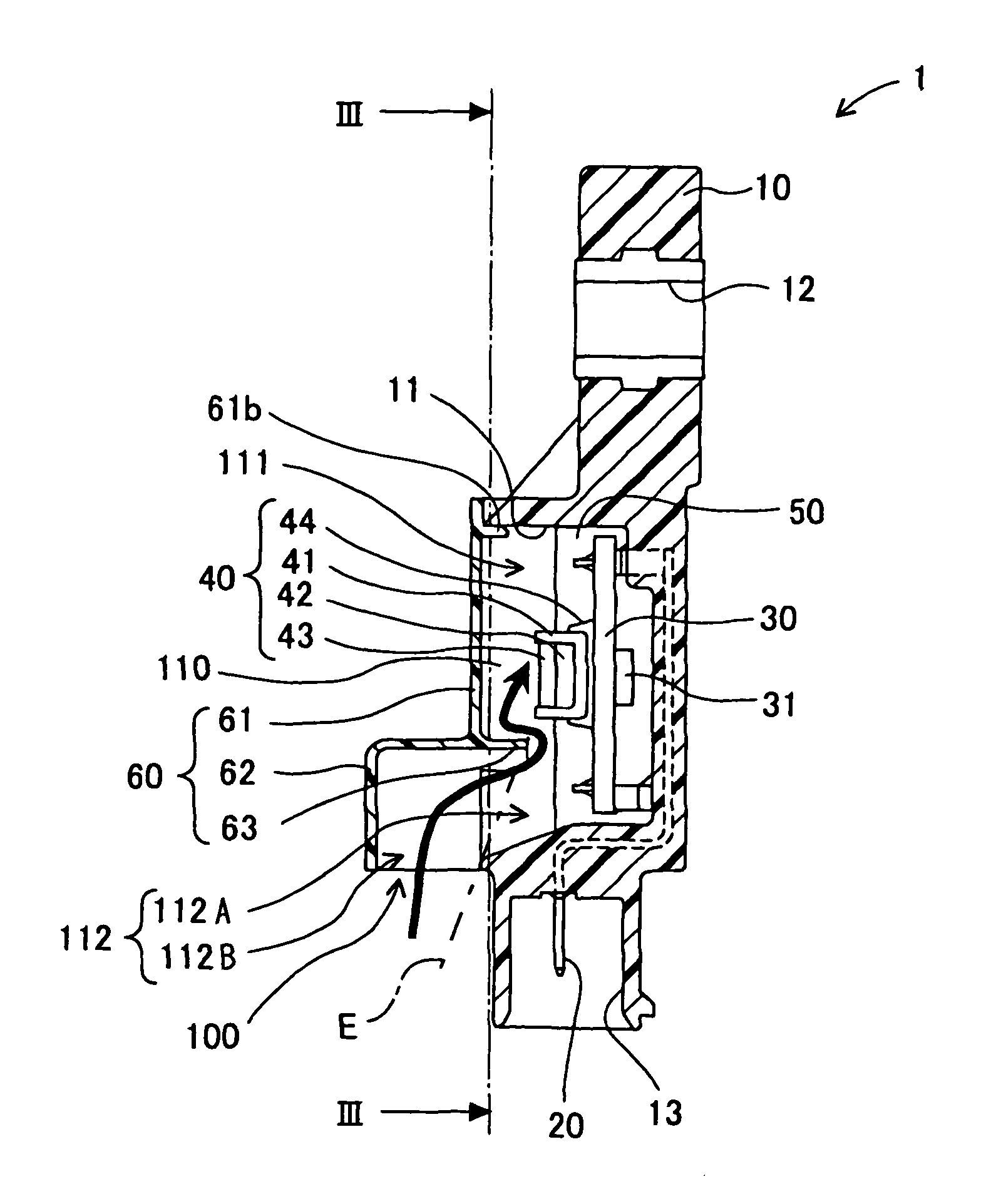
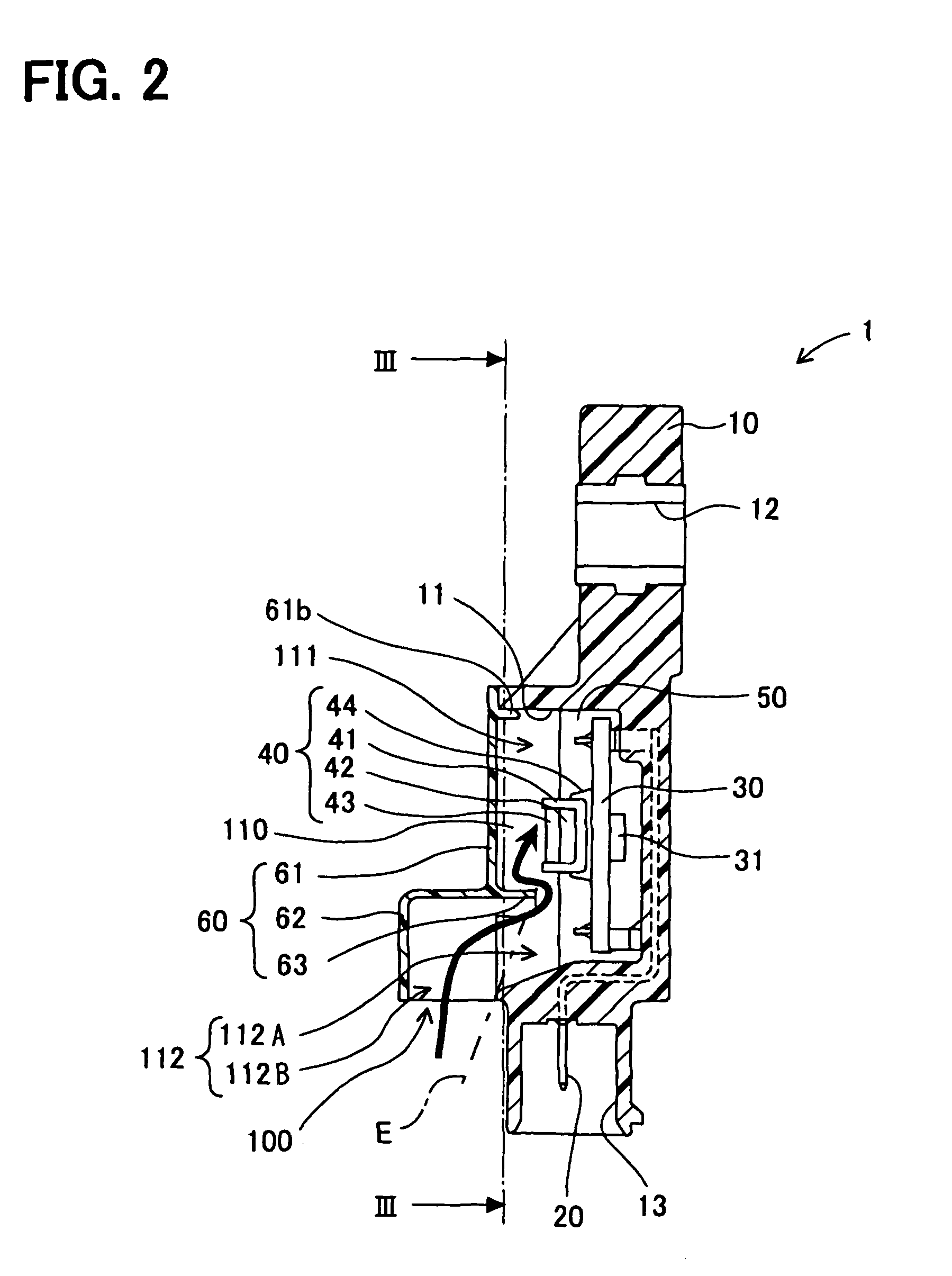
[0025]A pressure sensor 1 according to an example embodiment is described below with reference to FIGS. 1 to 3.

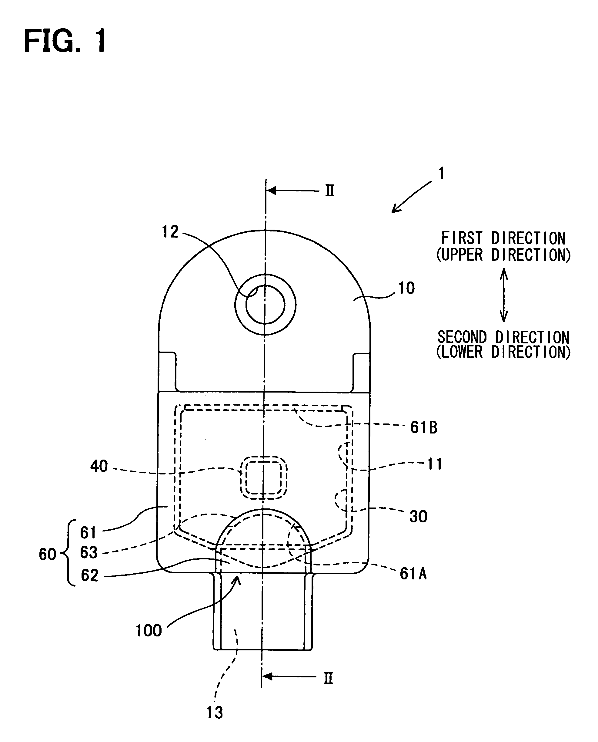
[0026]The pressure sensor 1 can be used as a sensor that is disposed in an internal space of a door of a vehicle, and that detects a change in pressure of the internal space of the door to sense a collision between the door of the vehicle and an object. In addition, when the pressure sensor 1 is mounted in the door of the vehicle, first and second directions of the pressure sensor 1 shown in FIG. 1, respectively, correspond to an upper direction and a lower direction of the vehicle.

[0027]For the above-described reasons, it is assumed in the following description that the first and second directions associated with the pressure sensor 1 correspond to an upper direction and a lower direction, respectively. In addition, it is assumed that the view direction of the pressure sensor 1 in FIG. 1 corresponds to a lateral direction of the vehicle.

[0028]As shown in FIGS. 1 to 3, the ...


PUM

PropertyMeasurementUnit
areaaaaaaaaaaa
pressureaaaaaaaaaa
temperatureaaaaaaaaaa

Abstract

A pressure sensor is provided. The pressure sensor includes a body, a sensing element, and a projection part. The body has an internal space and an introduction passage. The internal space is in communication with an outside of the body through the introduction passage. The sensing element is disposed in the internal space of the body and capable of detecting pressure of air in the internal space. The projection part is disposed in the internal space of the body or the introduction passage of the body, and inhibits liquid from entering the internal space.

Description

CROSS REFERENCE TO RELATED APPLICATION[0001]The present application is based on Japanese Patent Application No. 2007-206968 filed on Aug. 8 2007, the disclosure of which is incorporated herein by reference.BACKGROUND OF THE INVENTION[0002]1. Field of the Invention[0003]The present invention relates to a pressure sensor.[0004]2. Description of Related Art[0005]Patent Document 1 recites a pressure sensor. According to Patent Document 1, a pressure sensor is disposed in an internal space of a door of a vehicle in order to sense a collision taking place at a side of the vehicle. When an object collides with the door, the pressure sensor senses a change in pressure of the internal space of the door. For detection of such pressure change, the pressure sensor includes an introduction passage. The introduction passage introduces the air in the internal space of the door into a pressure detection surface of the pressure sensor. The introduction passage is formed to extend in a direction perp...

Claims


Application Information

Patent Timeline
Patent Type & Authority Patents(United States)
IPC IPC(8): G01L7/00
CPCG01L19/141G01L19/0084G01L19/0654G01L19/0038B60R21/0136B60R2021/0006
Inventor WATANABE, TATSUYA
Owner DENSO CORP
Why Eureka
Try Eureka