Apparatus for injection molding
a technology of injection molding and apparatus, which is applied in the field of injection molding, can solve the problems of inability to substitute, inability to meet the requirements of ineffective use of threaded engagement for retaining nozzles with manifold members,
- Summary
- Abstract
- Description
- Claims
- Application Information
AI Technical Summary
Benefits of technology
Problems solved by technology
Method used
Image
Examples
fourth embodiment
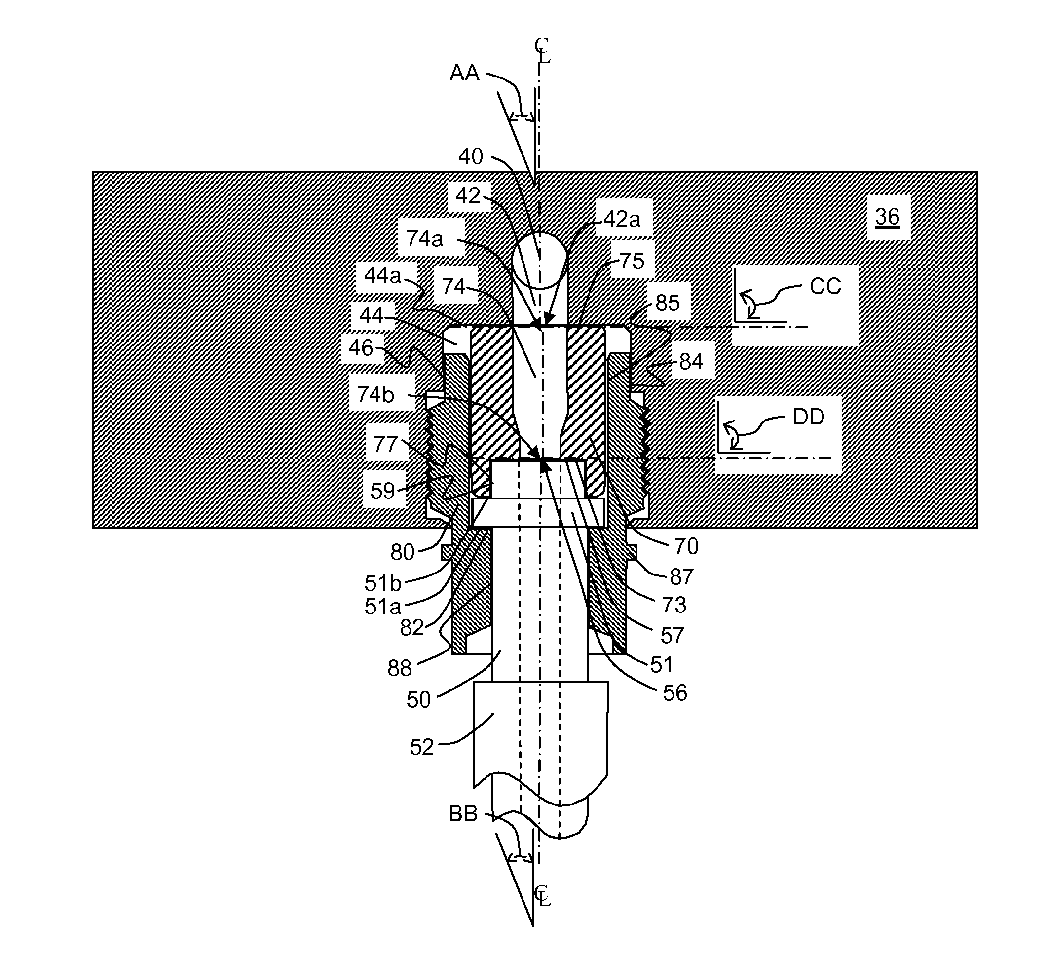
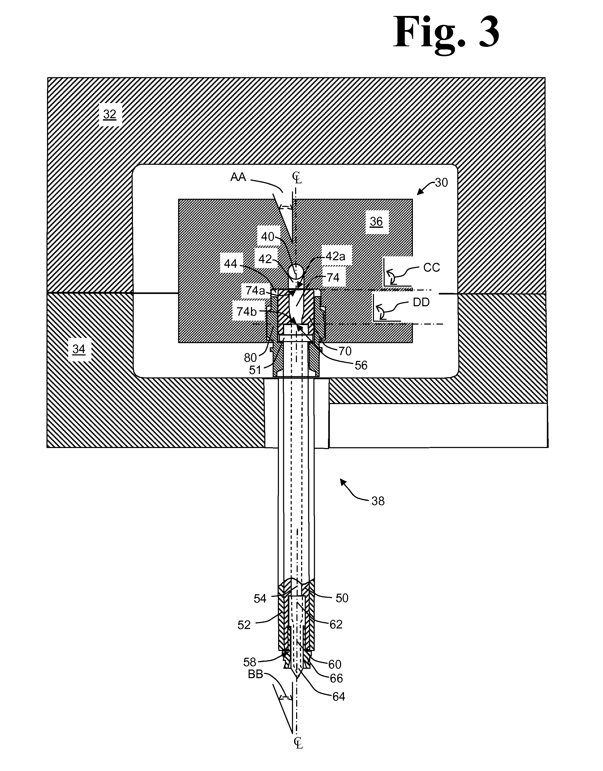
[0037]Referring to FIGS. 7a and 7b, particular aspects of the arrangement of an adaptor bushing, retention device and nozzle assembly effective for retention and alignment of an adaptor bushing and nozzle assembly with manifold block 36 will be described. In FIG. 7b, a portion of nozzle body 50 is shown in phantom (dashed lines). As in the first three embodiments, communicating passage 42 terminates in outlet 42a at ceiling 44a of receiving bore 44. The inlet end of nozzle assembly 38 is partially received in receiving bore 44 and adaptor bushing 170 is interposed between manifold block 36 and nozzle assembly 38. Internal shoulder 182 of nozzle retaining nut 180 engages lower external shoulder 51a comprising nozzle body 50 on the nozzle outlet side of nozzle body flange 51. External threads, such as threads 181, of nozzle retaining nut 180 engage internal threads of nozzle receiving bore 44 of manifold block 36 to retain nozzle body 50 with manifold block 36. Adaptor bushing 170 is ...
second embodiment
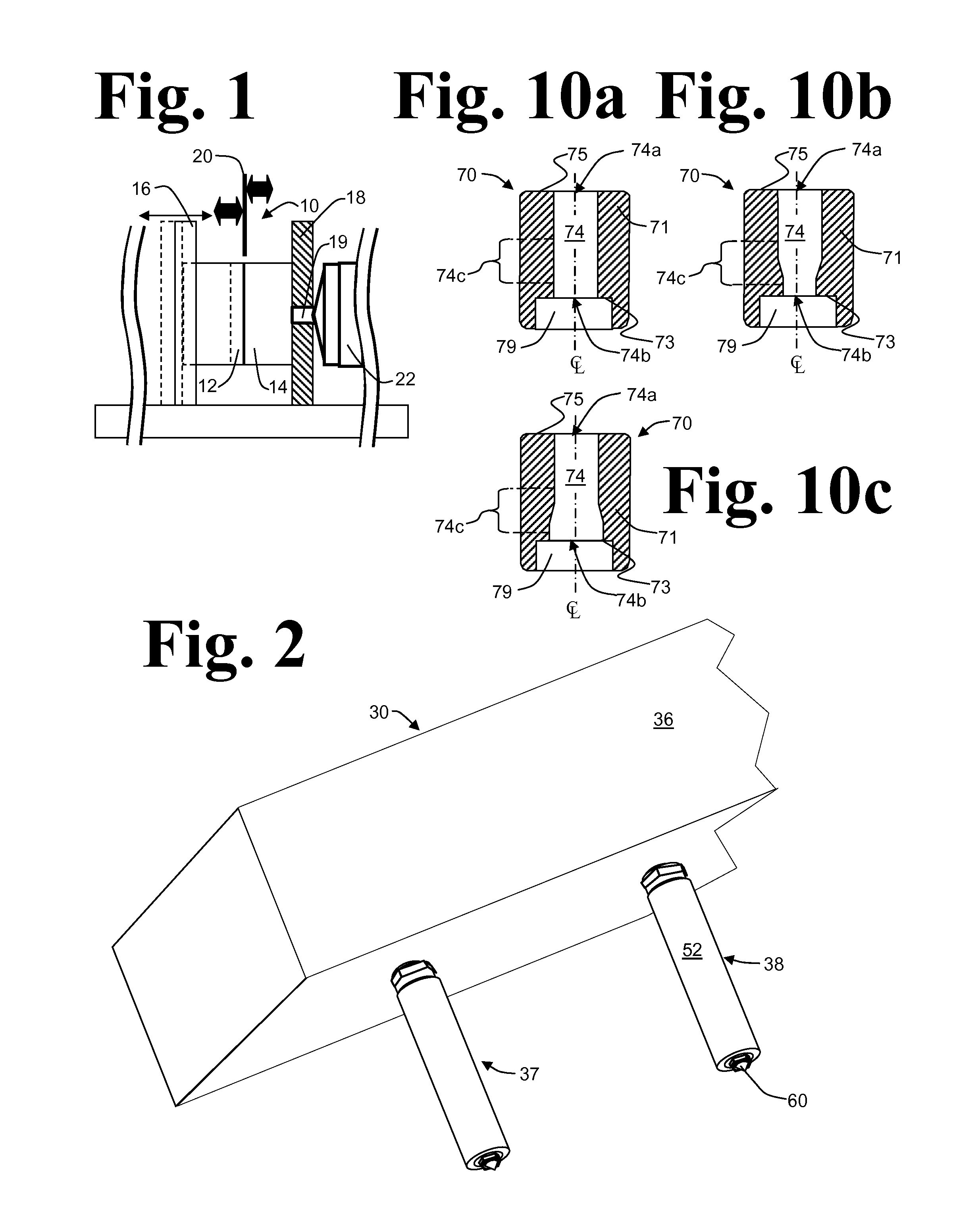
[0038]Continuing with reference to FIGS. 7a and 7b, as in the second embodiment, bushing recess 179 provides clearance for the sidewall of the nozzle inlet end projection so that there is either no, or only incidental, contact between the sidewall of bushing recess 179 and nozzle body 50. Sealing contact of opposed surfaces of manifold block 36 and bushing body 171 occurs by contact of end face 175, comprising a surface surrounding bushing inlet 174a, with ceiling 44a comprising a surface surrounding the communicating passage outlet 42a. Sealing contact of opposed surfaces of bushing body 171 and nozzle body 50 occurs by contact of recessed face 173 comprising a surface surrounding outlet 174b of bushing passage 174 with the inlet end face 57 of nozzle body 50 comprising a surface surrounding nozzle inlet 56. With compressive forces effected by engagement of retaining nut 180 with receiving bore 44 and acting parallel to the longitudinal centerline of bushing body 170, sufficient se...
fifth embodiment
[0041]the invention substantially similar to the fourth embodiment shall be described with reference to FIGS. 8a and 8b. Unlike the fourth embodiment of the invention, retaining nut 180 of the fifth embodiment lacks nozzle alignment surface 188 located on the interior of retaining nut 180 below internal shoulder 182 and the internal sidewall 189 of retaining nut 180 provides clearance for nozzle body 50 below shoulder 182 so that there is no, or only incidental contact with nozzle body 50 and sidewall 189 of retaining nut 180. Similarly to the fourth embodiment, adaptor bushing 170 comprises second bushing external alignment surface 176 disposed on the exterior of the trunk 171b of adaptor bushing 170 at a location to contact complementary internal bushing alignment surface 186 comprising interior sidewall 185 of retaining nut 180. In the fifth embodiment, receiving recess 179 of bushing body 171 comprises internal alignment surface 177 disposed on the sidewall of nozzle receiving r...
PUM
| Property | Measurement | Unit |
|---|---|---|
| size | aaaaa | aaaaa |
| melt | aaaaa | aaaaa |
| cross-sectional sizes | aaaaa | aaaaa |
Abstract
Description
Claims
Application Information
 - R&D
- Intellectual Property
- Life Sciences
- Materials
- Tech Scout
- Unparalleled Data Quality
- Higher Quality Content
- 60% Fewer Hallucinations
Browse by: Latest US Patents, China's latest patents, Technical Efficacy Thesaurus, Application Domain, Technology Topic, Popular Technical Reports.
© 2025 PatSnap. All rights reserved.Legal|Privacy policy|Modern Slavery Act Transparency Statement|Sitemap|About US| Contact US: help@patsnap.com


