Reciprocating wind-powered transducer employing interleaved airfoil arrays

a wind-powered transducer and interleaved technology, applied in the direction of electric generator control, machines/engines, mechanical equipment, etc., can solve the problems of unattractive industrial heat exchanger facilities and exhaust fans, unsuitable, and blocked airflow

Inactive Publication Date: 2012-10-02
ARNTZ FLOYD
View PDF23 Cites 25 Cited by
  • Summary
  • Abstract
  • Description
  • Claims
  • Application Information

AI Technical Summary

Benefits of technology

[0040]In accordance with a third aspect of the device, it includes means for tilting the blades to a second position so that, during a second stroke of the transducer, the leading edge of each blade of the second set is tilted upward away from the leading edge of each blade of the first set, which is tilted downward, so that the passage of the fluid causes the blades of the second set to linearly rise and the blades of the first set to linearly fall, creating linear excursions thereby.
[0044]In accordance with a seventh aspect of the device, the blades are airfoils capable of creating lift as a result of fluids flowing over their surfaces, and the angles at which they are tilted provides Bernoulli-effect forces which drive apart those blades whose leading edges are tilted away from the leading edges of adjacent blades.
[0053]In accordance with a sixteenth aspect of the device means are provided to move the tilt rods up and down, thereby changing the attitude of the blades.

Problems solved by technology

As the blades approach one another one may consider invoking aerodynamic analysis applicable to the biplane, but this is not applicable because in this case nearest neighbor blades are tilted in opposition and are converging with their nearest neighbors.
Furthermore, in the extreme, momentarily the airflow may be blocked altogether.
In addition to providing electrical power or driving reciprocating heat pumps they would conceal from view unattractive industrial heat exchanger facilities and exhaust fans typically installed there.
A significant difference between this transducer and the IC engine is that for each airfoil array both strokes comprising a full single cycle impart power to the load whereas in a two-stroke IC engine only one stroke is a power stroke, the other is a power-consuming compression stroke.

Method used


Image

  • Reciprocating wind-powered transducer employing interleaved airfoil arrays
  • Reciprocating wind-powered transducer employing interleaved airfoil arrays
  • Reciprocating wind-powered transducer employing interleaved airfoil arrays

Examples


Embodiment Construction

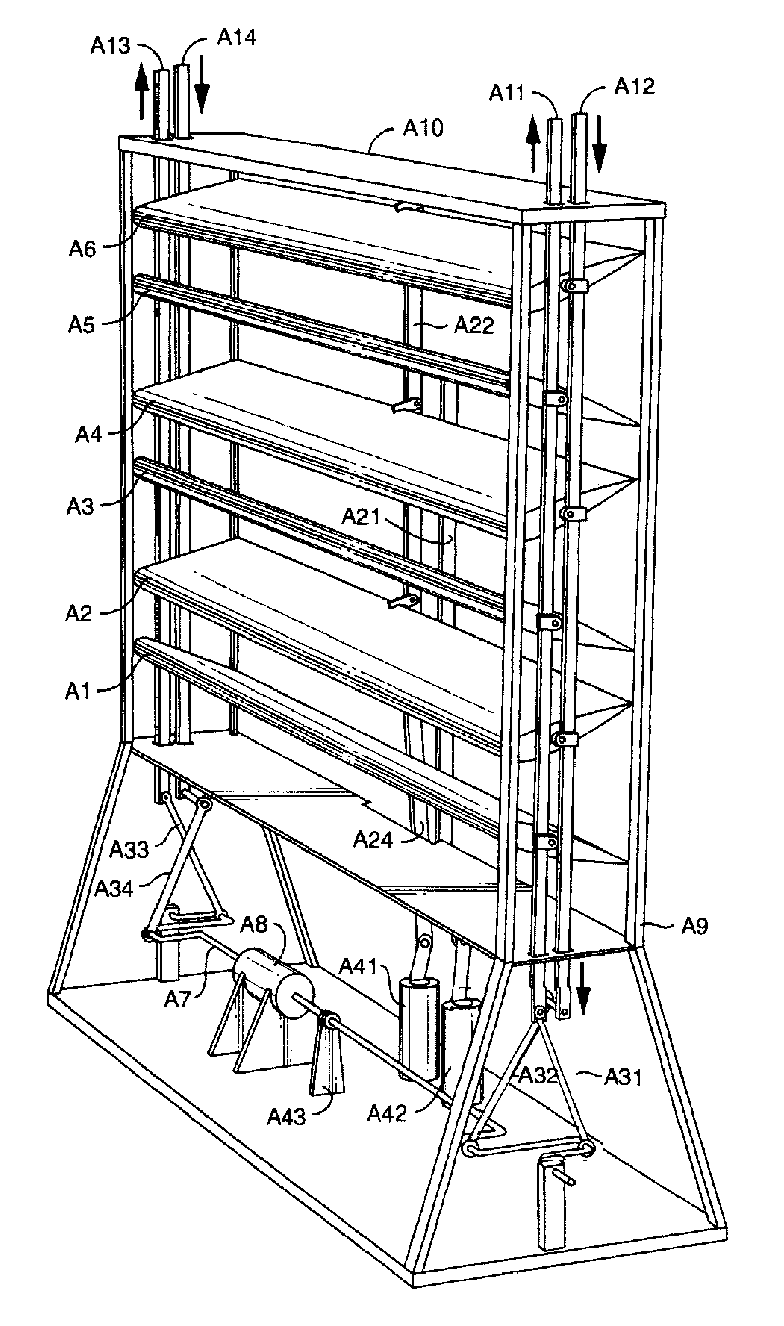
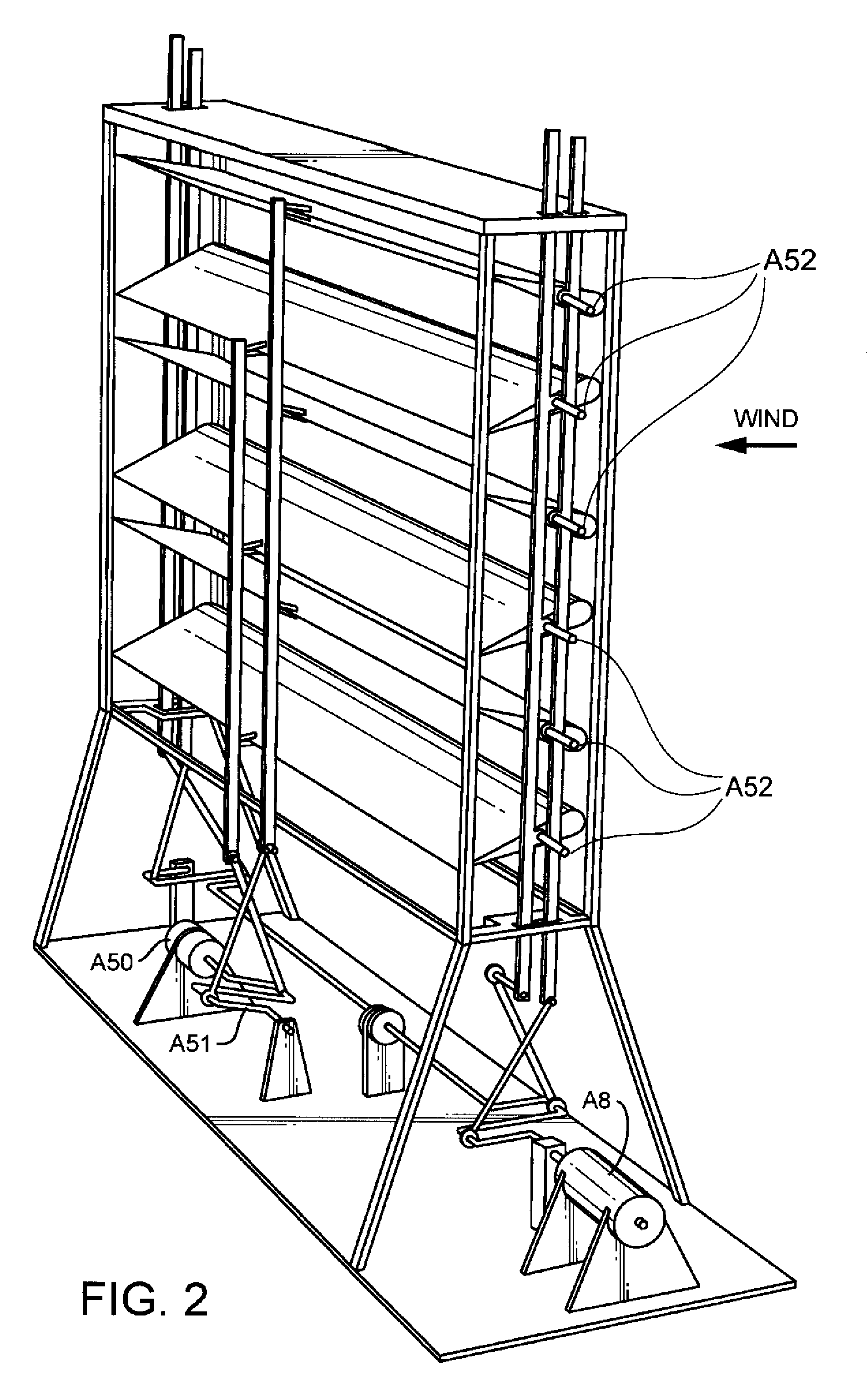
[0083]Referring first to FIG. 1, a first embodiment of the transducer, in the form of a wind-powered array, is shown.

[0084]The array includes an odd numbered set of blades (A1, A3, A5) comprise the odd sub-array, and an even numbered set of blades (A2,A4,A6) comprise the even sub-array. The blades in this embodiment are in the form of airfoils.

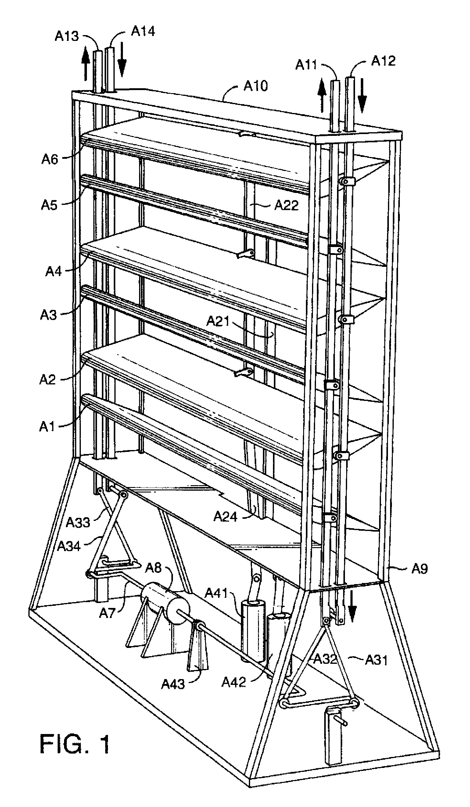
[0085]Blades A1,A3,A5 are pivotably coupled at their ends to thrust rods A11, A13 by means of spars A52, FIG. 2, and pivotably coupled at their trailing edges to tilt rod A21. Similarly blades A2,A4,A6 are coupled at their ends to rods A12, A14, and coupled at their trailing edges to tilt rod A22.

[0086]In analogy with two-stroke in-line internal combustion engines, thrust rods A11, A13 are pivotably coupled to connecting rods A31, A33 with “wrist” bearings at one end of each, the other ends pivotably coupled to opposing crank pins on the flat crankshaft A7. Correspondingly the even numbered blades (A2, A4, A6), comprising the even blade sub-ar...


PUM


Abstract

A reciprocating transducer to convert windpower to electrical energy includes an odd sub-array of blades and an even sub-array of blades, wherein two odd thrust rods are pivotably coupled to the ends of each of the odd numbered blades, two even thrust rods are pivotably coupled to the ends of each of the even numbered blades, an odd tilt rod is pivotably coupled to the trailing edge of each of the odd numbered blades, an even tilt rod is pivotably coupled to the trailing edge of each of the even numbered blades. The tilt rods are moved up and down, thereby changing the attitude of the blades, a crank shaft converts the linear motion of the thrust rods into rotational motion, and a generator converts the rotational motion into electrical power.

Description

[0001]The application claims priority based on U.S. Provisional Application No. 61 / 465,353.DESCRIPTION IN VIEW OF RELEVANT ART[0002]The present device is a reciprocating transducer designed to convert the kinetic energy in a moving fluid into electrical energy. The device is especially suited for use to convert wind into electrical power.[0003]Prior relevant technology of this nature has emphasized the use of rotating turbines, which are presently in use in an expanding market. However, wind turbines have a number of drawbacks. They are large and expensive to operate and install, are not practical for use in connection with many types of residences, and are known to pose a danger to birds.[0004]The present device, in contrast, can be quite compact and light-weight, and suitable for mounting on the ground, in back yards of residences, or on roof tops, as well as presenting other mounting alternatives.[0005]Common to all the embodiments of this device are two interleaved arrays of air...

Claims


Application Information

Patent Timeline
Patent Type & Authority Patents(United States)
IPC IPC(8): F03B13/00H02P9/04
CPCF03D5/00Y02E10/725Y02E10/70F05B2260/506Y02E10/72
Inventor ARNTZ, FLOYD
Owner ARNTZ FLOYD
Why Eureka
Try Eureka