

Spark arrestor for processing railroad rails
a technology for arrestors and railroads, applied in the field of spark arrestors, can solve the problems of not being able to meet the needs of domestic applications, not being able to meet the needs of service, not being able to treat fire resistance, etc., and achieving economic feasibility, effective and effective solutions.
Inactive Publication Date: 2012-10-09
MOYER DENNIS
View PDF10 Cites 3 Cited by
- Summary
- Abstract
- Description
- Claims
- Application Information
AI Technical Summary
Benefits of technology
Substantially reduces or eliminates burn hazards and fire risks to workers and surrounding materials, while being economical and easy to use, with the design allowing direct viewing of the torch and accommodating various rail positions.
Problems solved by technology
In connection with conventional railroad operations, it is periodically necessary to remove railroad rails which have become worn or otherwise deteriorated and are not serviceable with the degree of safety required.
The ties are not fire resistant and are not treated to be fire resistant.
While prior efforts have been made to deal with this serious problem of flames and sparks, to-date none have provided a successful, economically feasible, technically effective solution.
The structure is not suitable for use in the present invention's environment, as there is no way of providing seals underlying the lower edge of the shield.
Also, there is no way of providing continuity of protection, as there is no position in which a rail could pass through the structure.
Method used
View moreImage
Smart ImageViewing Examples

Examples
example
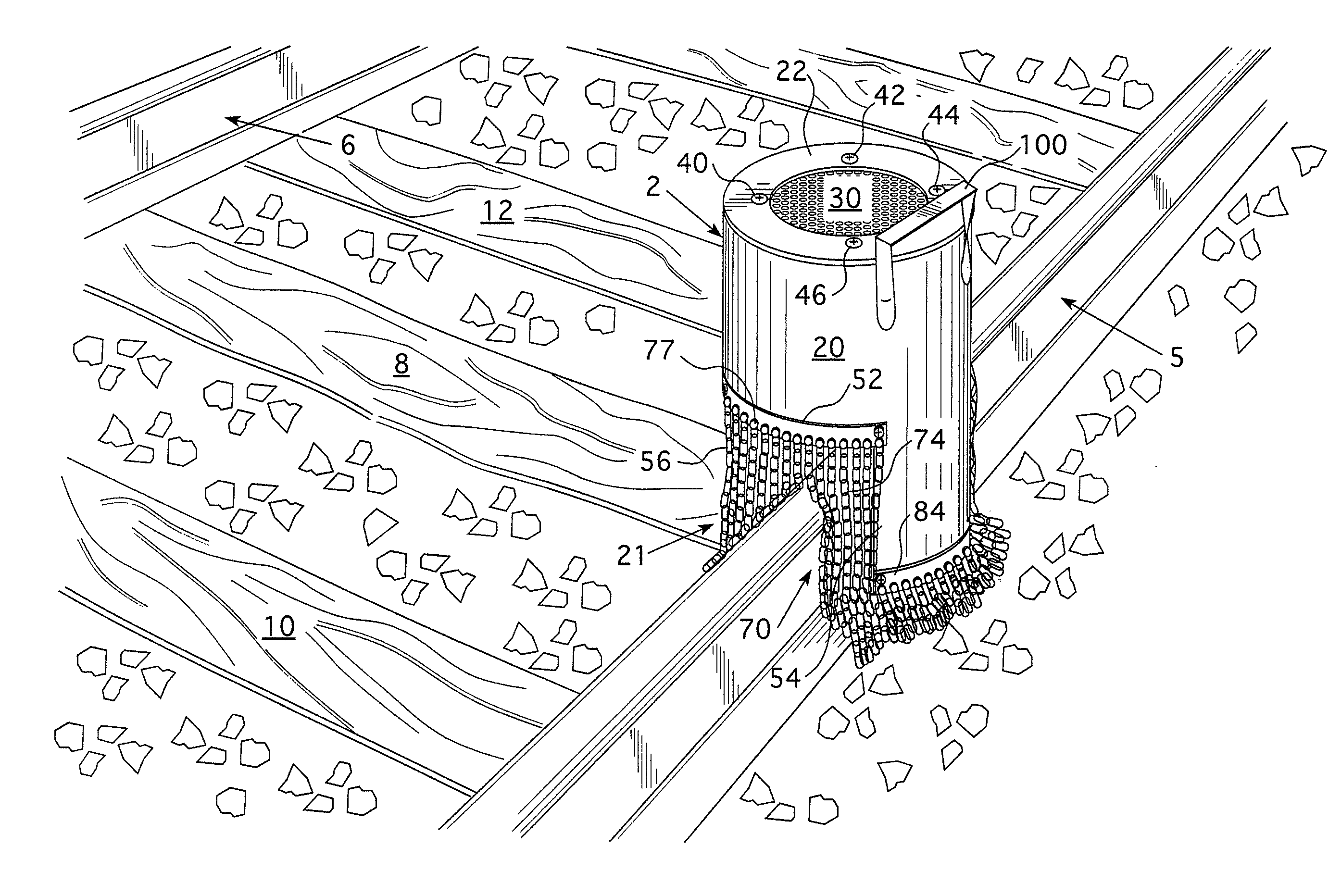
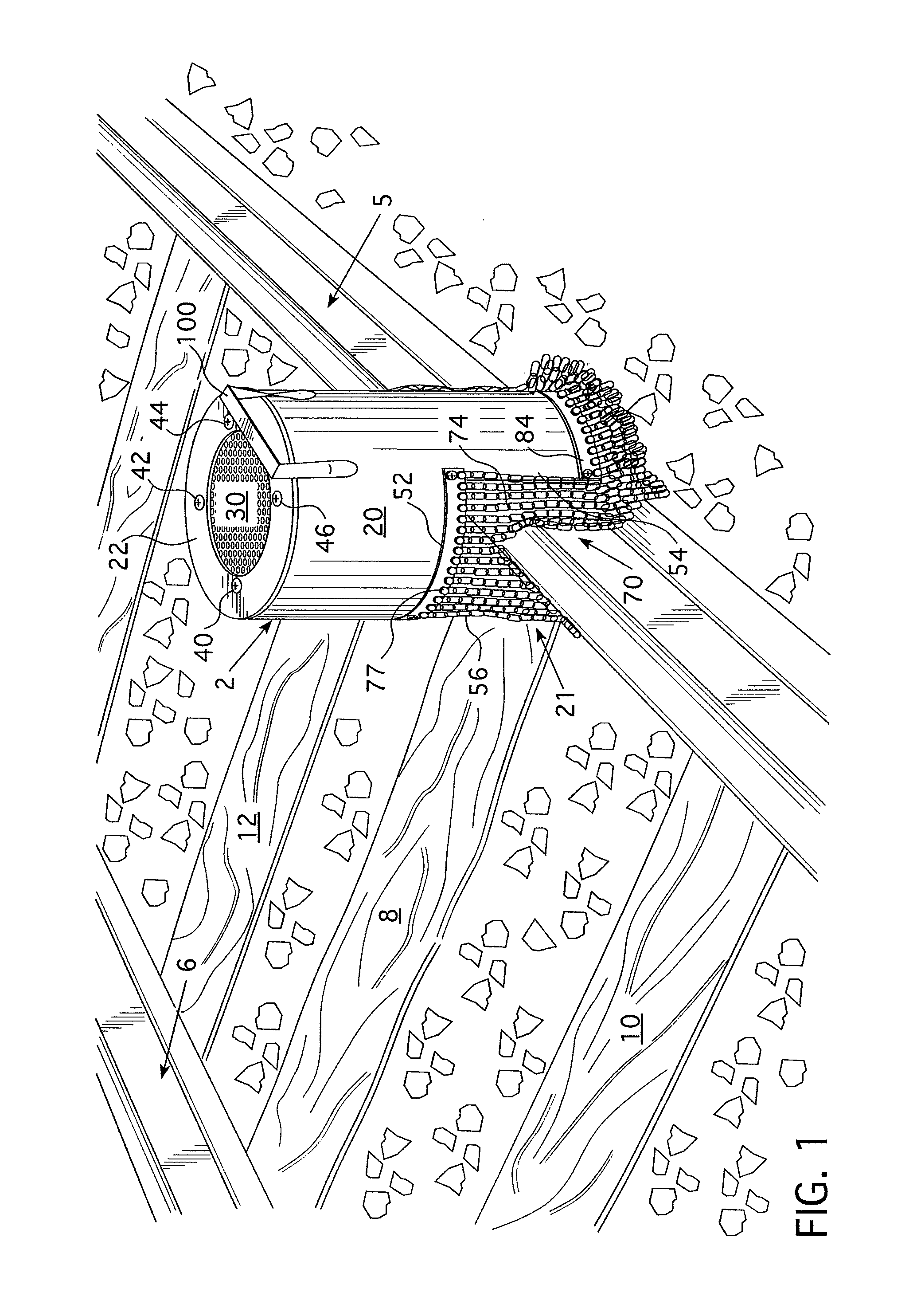
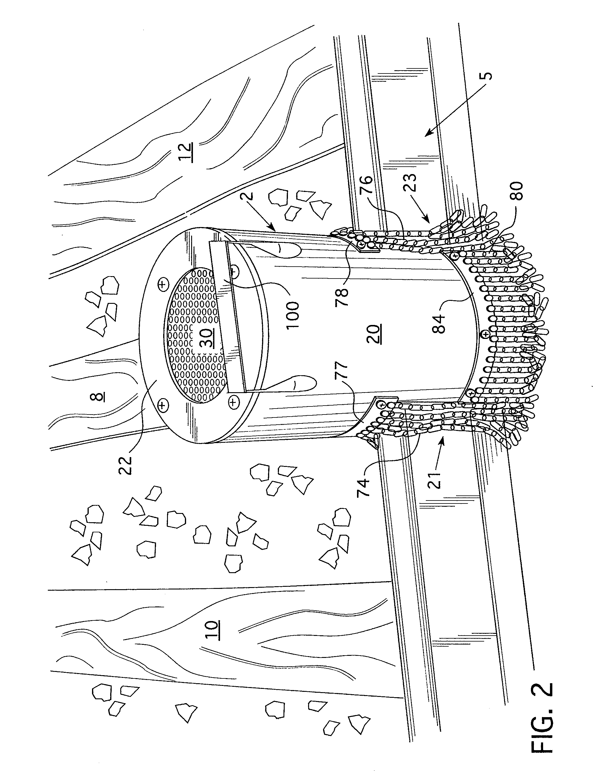
[0047]A non-limiting example of a currently preferred dimensional range for the shield is as follows. The overall axial height of the shield will be about 15 to 21 inches and the transverse diameter measured on the exterior will be about 9 to 13 inches. The openings for the rails will each be about 6 to 10 inches wide and will have a height of about 6 to 10 inches. The opening at the upper end will be about 6 to 8 inches across. Preferably, two stainless steel mesh grills, such as 30, will be provided in the top opening spaced from each other about ½ inch and having the patterns slightly offset from each other. The torch window 50 (FIG. 3) will preferably be an opening of about 2 to 4 inches wide and 6 to 8 inches high.
Login to View More PUM
 Abstract
A spark arrestor for processing railroad rails includes an annular body having an upper end wall provided with a first opening and a lower end wall provided with a second opening. The annular body has a pair of generally aligned, circumferentially offset, downwardly open recesses, each structured to be received over a portion of the railroad rail and each having a first plurality of downwardly extending shield elements, extending downwardly beyond the upper surface of the rail. Lateral surfaces of the annular body disposed between the downwardly open recesses have a plurality of second shield elements extending downwardly therefrom. A cutting torch or heating torch or welding torch receiving opening is provided in the annular body to facilitate insertion of the torch. The upper and lower end wall opening, each preferably having a grid structure to resist outward migration of sparks and flames from the interior of the spark arrestor.
Description
BACKGROUND OF THE INVENTION[0001]1. Field of the Invention[0002]The present invention relates to a spark arrestor and, more specifically, it relates to a spark arrestor which may be employed in combination with a torch used to process portions of a railroad rail in the process of rail cutting, reclaiming or salvaging the railroad rail, or welding, or preheating the rail while focusing upon resisting undesired spreading of flames or sparks to adjacent people or material in order to minimize or eliminate the risk of employee burns and fires.[0003]2. Description of the Prior Art[0004]In connection with conventional railroad operations, it is periodically necessary to remove railroad rails which have become worn or otherwise deteriorated and are not serviceable with the degree of safety required. It is conventional to use a cutting torch to cut portions of the upper rail underlying the upper flange approximately every forty feet along the length of the rail.[0005]When cutting rail, the ...
Claims
Login to View More Application Information
Patent Timeline
 Patent Type & AuthorityPatents(United States)
IPC IPC(8): A62C8/00A47G5/04
CPCA62C8/08
InventorMOYER, DENNIS
OwnerMOYER DENNIS