Method of remediating a contaminated waste site

a waste site and remediation method technology, applied in the direction of loading/unloading vehicles, transportation items, nuclear engineering, etc., can solve the problems of unavoidably increasing overhead costs and delay in the completion of the clean-up

Active Publication Date: 2012-10-09
AMEREN CORP
View PDF45 Cites 7 Cited by
  • Summary
  • Abstract
  • Description
  • Claims
  • Application Information

AI Technical Summary

Problems solved by technology

The process of disassembling the temporary building, moving it from one site area to another, and then re-assembling the building, is time-consuming, typically taking six or seven weeks.
As a result, completion of the clean-up is delayed.
Moreover, resources on the site, such as remediation equipment and personnel, consulting personnel, and air monitoring equipment and personnel, remain largely idle during the delay, which unavoidably increases overhead costs.

Method used


Image

  • Method of remediating a contaminated waste site
  • Method of remediating a contaminated waste site
  • Method of remediating a contaminated waste site

Examples


Embodiment Construction

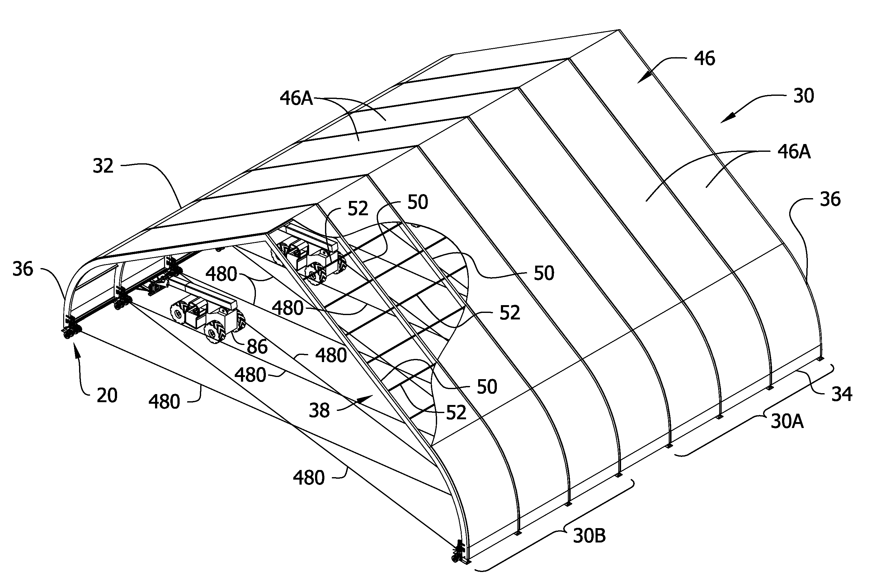
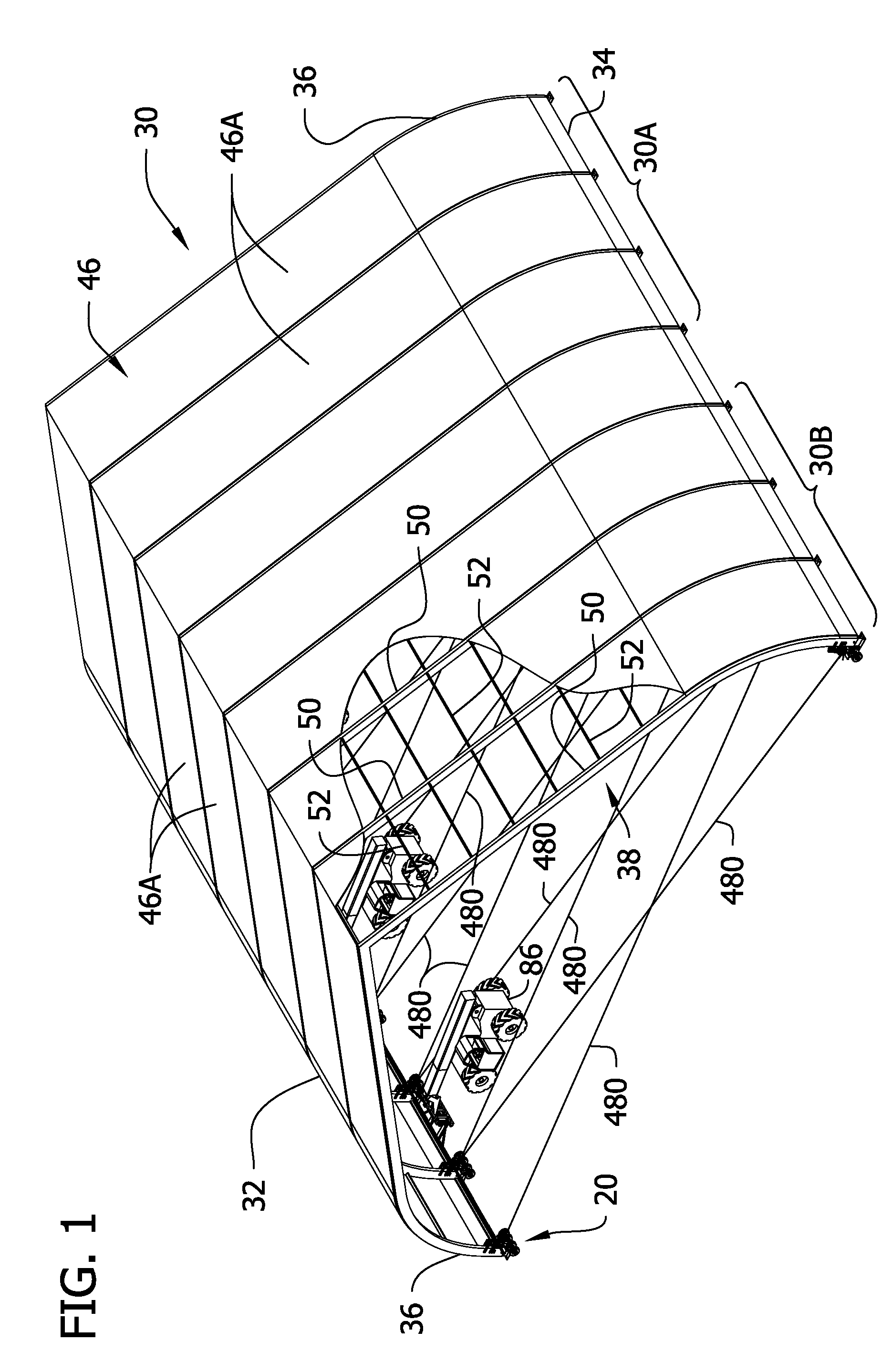
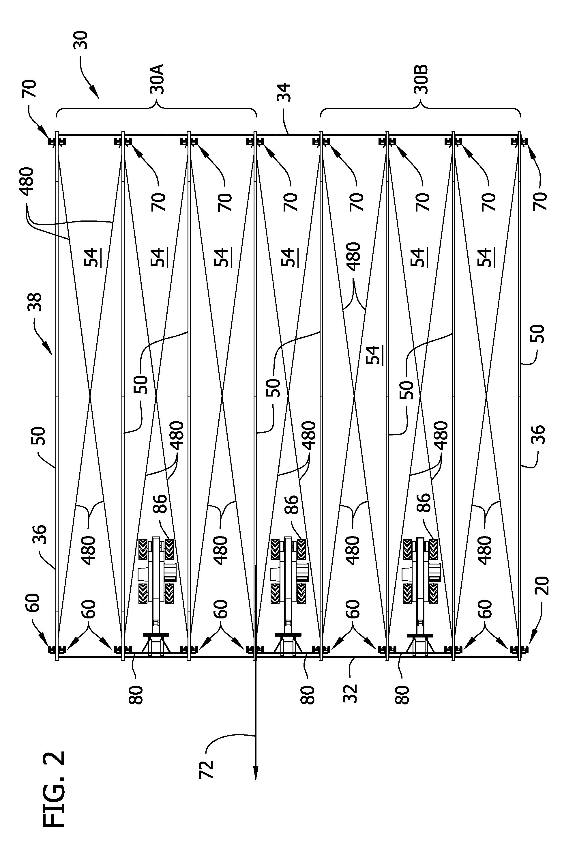
[0025]Referring to FIGS. 1 and 2, a transport system of this invention, generally designated 20, is used for moving a large temporary building from a first location to a second location. An example of one such building 30 is shown in FIG. 1. The building 30 is a large tent-like structure having a first side 32, a second side 34 opposite the first side, opposite ends 36, a frame generally designated 38, and a cover 46 supported by the frame to form a roof for the building. In the illustrated embodiment, the frame 38 comprises a plurality of rigid ribs configured as arches 50 lying in generally parallel vertical planes spaced at intervals along the length of the building 30. Purlins 52 (not shown in FIG. 2) connect the arches. The arches 50 divide the structure into separate bays or sections 54, seven such bays being shown in FIG. 2. The lower ends of the arches 50 are connected to foot plates 56 (see FIG. 12) for supporting the arches upright. The connection between each foot plate 5...


PUM


Abstract

A method and system for moving a large temporary building from a first location to a second location, while the building remains erect, are disclosed. The invention is particularly suited for moving such a building during the remediation of a contaminated waste site.

Description

FIELD OF THE INVENTION[0001]The present invention generally relates to systems and methods for moving large temporary buildings, including fabric structure buildings which can be used to remediate waste sites.BACKGROUND OF THE INVENTION[0002]The remediation of contaminated waste sites (e.g., manufactured gas plant (MPG) remediation) involves such conventional techniques as excavation and off-site disposal of wastes, chemical fixation, soil washing, in-situ thermal treatment, incineration of excavated soil and other technologies. In some instances, a large temporary building, resembling a large tent, is erected over a first area of the site, and clean-up activities are carried out inside the tent to contain fugitive air emissions. The size of the tent-like building can vary, e.g., from 20-40 meters or more wide and 20-60 meters or more long. After clean-up of the first area is finished, the tent is disassembled, moved to a second area of the site, and re-assembled so that clean-up ca...

Claims


Application Information

Patent Timeline
Patent Type & Authority Patents(United States)
IPC IPC(8): E04G21/14
CPCB08B15/023B66F9/06
Inventor BURNS, STEVEN LEEINGRAM, DEREK D.LINNEMANN, JOHN D.DEEKE, STANLEY E.TARDREW, JEFFREY K.
Owner AMEREN CORP
Why Eureka
Try Eureka