Burner

a burner and burner port technology, applied in the field of burners, can solve the problems of insufficient mixing of fuel gas and primary air, large burner size cannot be used for gas combustion appliances, and the force to take in primary air is decreased, so as to reduce the ejection speed of mixed gas from the burner port, reduce the suction amount of primary air, and compact size

Active Publication Date: 2012-10-09
PALOMA
View PDF38 Cites 0 Cited by
  • Summary
  • Abstract
  • Description
  • Claims
  • Application Information

AI Technical Summary

Benefits of technology

[0010]A third aspect of the invention includes, in addition to the first and second aspects, a burner head which is in a cylindrical shape having a plurality of burner ports bored on almost whole periphery of a side face of the burner head, and is provided right above the mixing chamber of the burner main body, in order to have a sufficient burner port area thereby smoothly supplying mixed gas.
[0012]According to the first aspect of the invention, due to the extension pipe being provided in the burner main body, a distance for mixing can be sufficiently secured inside the burner. Furthermore, since an eddy flow does not occur when the mixed gas flows into the mixing chamber from the mixing pipe, the necessary primary air can be taken in using ejection energy of fuel gas, and thus the fuel gas and air needed for combustion can be favorably mixed in the mixing chamber. Therefore, the burner can be used as an all-primary air burner which has a compact size as a whole.
[0013]According to the second aspect of the invention, in addition to the effect of the first aspect, a favorable extension pipe, in which the suction amount of the primary air is increased, can be obtained by cutting the opening in inclining shape so as to have an upward opening.
[0014]According to the third aspect of the invention, in addition to the effects of the first and second aspects, a sufficient burner port area as an all-primary air burner can be kept with the cylindrical burner head. Further, an ejection speed of the mixed gas from the burner port is decreased, and thus fluid resistance is be suppressed. In addition to this, the mixed gas can be smoothly, uniformly supplied from the mixing chamber to the burner head. Further, since a combustion face is the side face, material debris dropping from an upper side are not accumulated on the burner port.
[0015]According to the forth aspect of the invention, in addition to the effect of any one of the first to third aspects, the extension pipe can be easily provided using the internal pipe.

Problems solved by technology

However, a large size of a burner cannot be used for a gas combustion appliance where only small installing space is available in a mixing chamber, such as a hot water storage type water heater.
Thus, the force to take in the primary air is decreased, and mixing of the fuel gas with the primary air becomes insufficient.

Method used


Image

  • Burner
  • Burner
  • Burner

Examples


Embodiment Construction

[0022]Embodiments of the present invention will be described below with reference to the drawings.

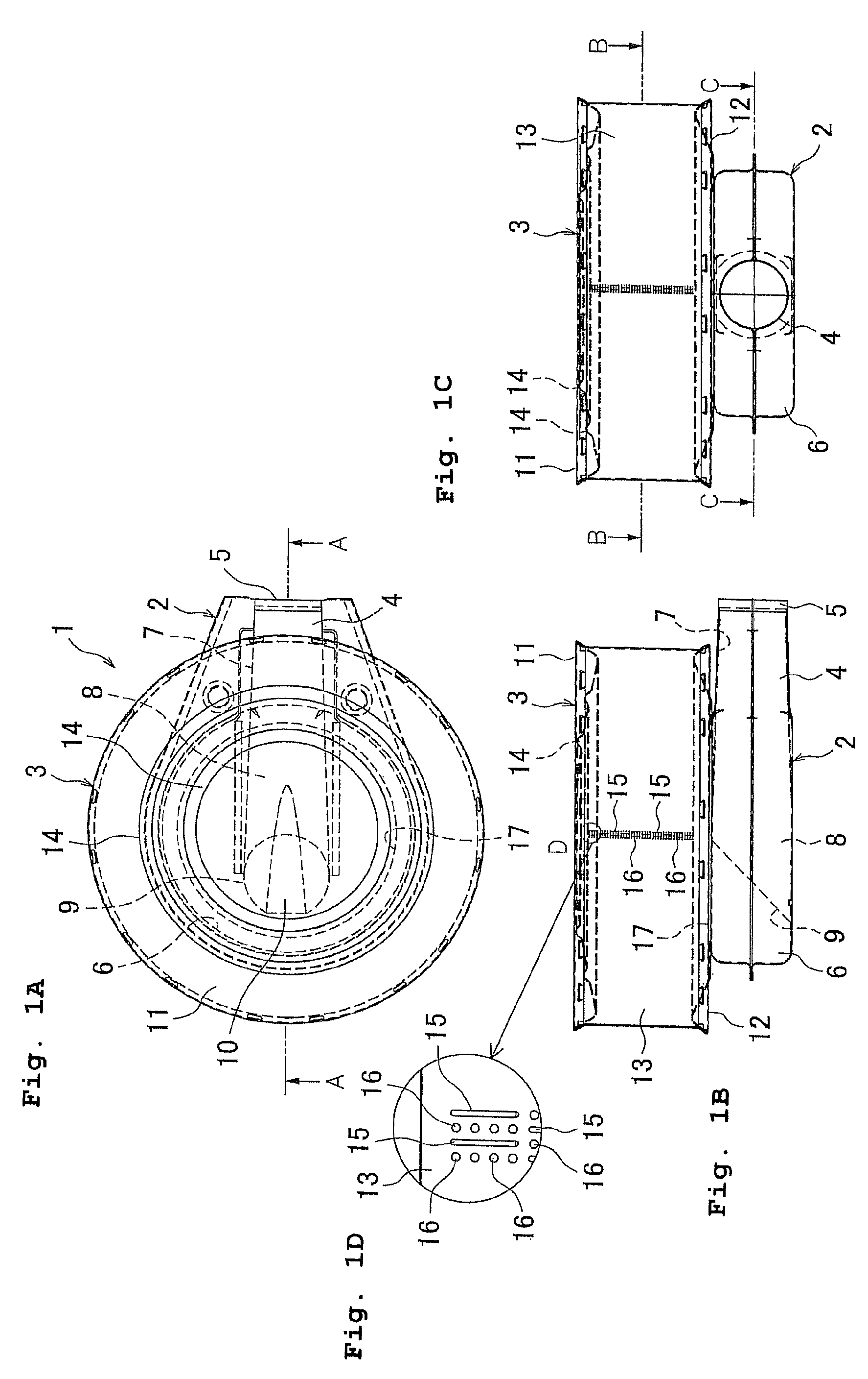
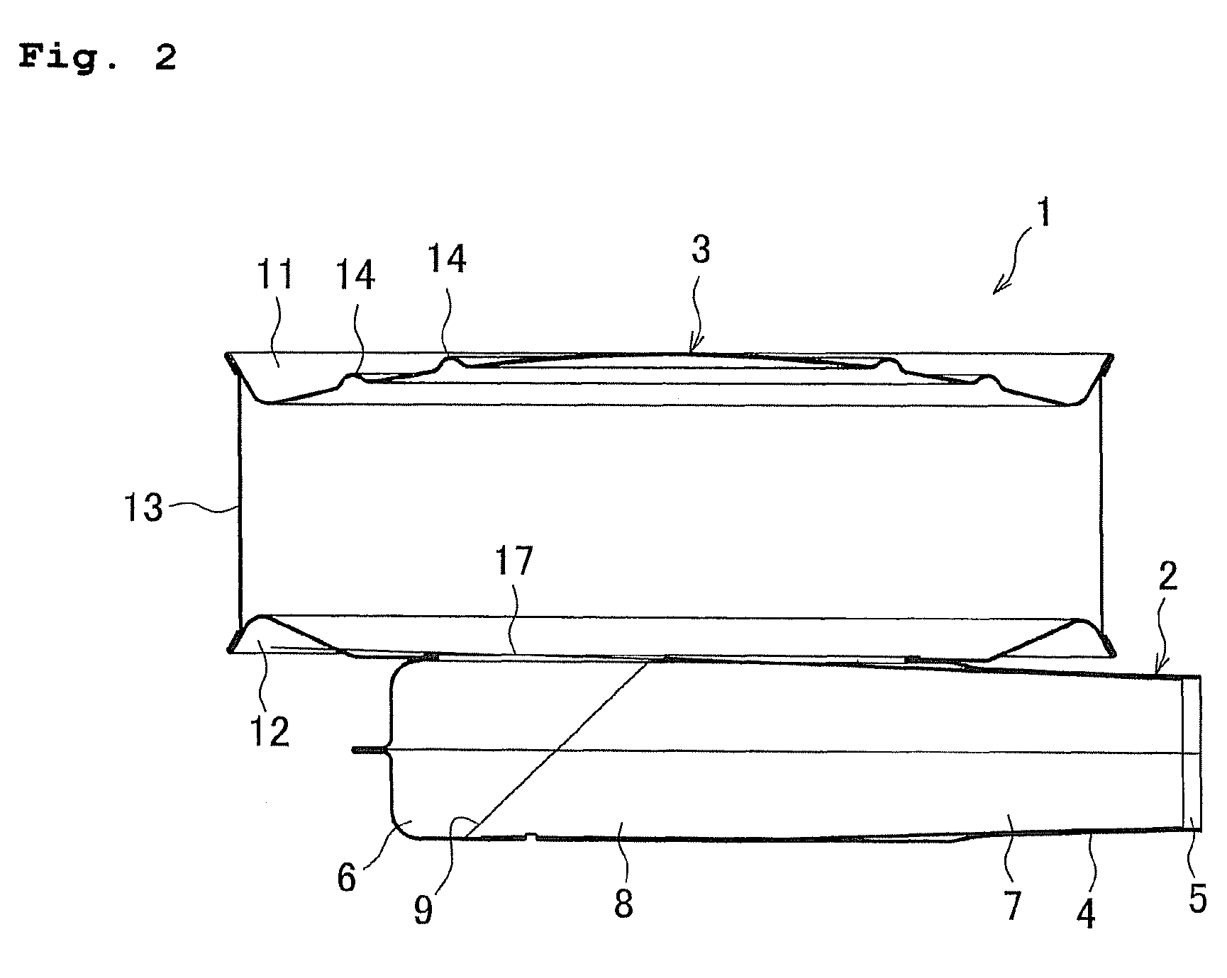
[0023]FIG. 1 are descriptive views of a burner, and FIG. 1A illustrates a plane view, FIG. 1B illustrates a front view, and FIG. 1C illustrates a right side face, respectively. A burner 1 includes a burner main body 2 on a lower side thereof, and a burner head 3 placed on the burner main body 2. The burner main body 2 includes a cylindrical mixing pipe 4 at an end part thereof, having a throat part 5, to which fuel gas and combustion air are supplied, and a round shaped mixing chamber 6 continuously provided at a downstream end of the mixing pipe 4. The burner main body 2 is formed with a pair of upper and lower metal plates which are bonded by caulking at a center thereof along the whole periphery. The mixing chamber 6 is a space having a radius larger than that of the mixing pipe 4, and continuously provided to the mixing pipe 4 in such a way that an axis line of the mixing pipe 4 in ...


PUM


Abstract

The object is to provide a burner capable of taking in sufficient primary air even though the size thereof is compact, and capable of being used as an all-primary air burner. A burner includes a mixing pipe to which a fuel gas and combustion air are supplied, a burner main body having a mixing chamber at a top end on a downstream side of the mixing pipe, and a burner head which is provided at an upper part of the burner main body while communicating with the mixing chamber and has first and second burner ports for ejecting mixed gas of the fuel gas and air for combustion mixed in the mixing chamber. The burner further includes an extension pipe in the burner main body protruding inside the mixing chamber being formed by extending the mixing pipe.

Description

BACKGROUND OF THE INVENTION[0001]This application claims the entire benefit of Japanese Patent Application Number 2007-119828 filed on Apr. 27, 2007, the entirety of which is incorporated by reference.FIELD OF THE INVENTION[0002]The present invention relates to a burner used for a gas combustion appliance such as a hot water storage type water heater.DESCRIPTION OF THE BACKGROUND ART[0003]A conventional burner includes a burner main body having a mixing pipe to which fuel gas and combustion air are supplied, and a mixing chamber provided at a top end on a downstream side of the mixing pipe. Further, the burner includes a burner head provided at an upper part of the burner main body while communicating with the mixing chamber and including a burner port for ejecting a mixed gas of the fuel gas and combustion air from the mixing chamber. For example, patent document 1 describes that a burner is used to heat hot and cold water and the like in a gas combustion appliance such as a hot wa...

Claims


Application Information

Patent Timeline
Patent Type & Authority Patents(United States)
IPC IPC(8): F23D14/62
CPCF23D14/065F23D14/46F23D14/583
Inventor ODA, HIROSHI
Owner PALOMA
Why Eureka
Try Eureka