System and method for removing surface contamination

a technology of surface contamination and system, applied in the direction of cleaning using liquids, instruments, applications, etc., can solve the problems of difficult and inefficient use, many surfaces become contaminated, and inhibit the use of surfaces, so as to reduce the turbulence of liquid flow and increase the visibility through the liquid flow

Inactive Publication Date: 2012-10-09
WIDEN RANDY MILES
View PDF16 Cites 7 Cited by
  • Summary
  • Abstract
  • Description
  • Claims
  • Application Information

AI Technical Summary

Benefits of technology

[0010]In another aspect, the invention provides a method for preventing or removing biofilms or other coatings of contaminants on a surface. The method includes providing an apparatus substantially as described, flowing a gas into the chamber so that a pressurized, laminar flow of gas flows from the chamber in a direction normal to the gas outlet orifice, and flowing a liquid from the liquid conduit through the liquid outlet orifice onto the surface so that the laminar gas flow propels the liquid in a laminar liquid flow across the surface. Advantageously, the liquid may be water, and the gas may be air. Optionally, but preferably, a surface tension reducer may be mixed into the stream of liquid upstream of the liquid outlet orifice, to reduce turbulence in the liquid flow (i.e., to make the liquid flow more laminar) and thus to increase visibility through the liquid flow.

Problems solved by technology

Many surfaces become contaminated during use with debris or other materials which inhibit use of the surface.
Often it is necessary to repeat the removal procedure periodically, interfering with and making use difficult and inefficient.
During use, the reflective surface of the mirror quickly becomes obscured from spray from the high-speed dental drill, dental material and tooth debris, fog, mist, etc.
This impaired reflective surface can lead to reduced workmanship in dental procedures unless the mirror is continually cleaned and / or a surface tension reducer is constantly applied.
This is both inconvenient and inefficient.

Method used


Image

  • System and method for removing surface contamination
  • System and method for removing surface contamination
  • System and method for removing surface contamination

Examples


Embodiment Construction

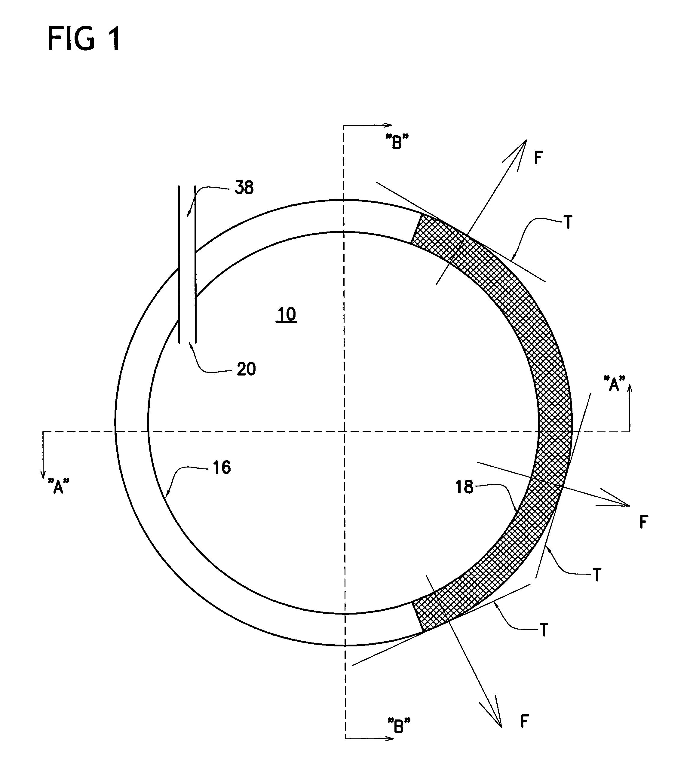
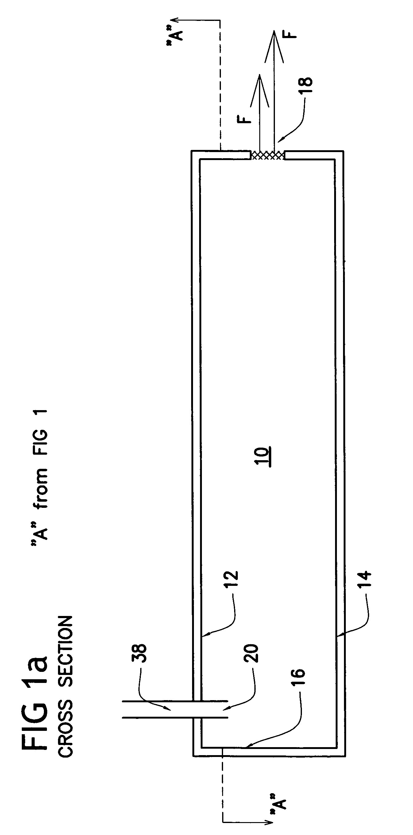
[0018]It is known in the art to use a flow of fluid, for example, air and / or water, to clear a surface of debris. An example of a device using this method is the dental mirror disclosed in applicant's U.S. Pat. No. 3,969,824, the disclosure of which is incorporated herein in its entirety by reference. The device disclosed in the earlier patent attempts to disperse the air flow coming down the handle / center air conduit by having the air hit a stationary obstruction that is air foil shaped, being thickest in the center and tapering toward the periphery.

[0019]Rather than using an airfoil-shaped obstruction in the fluid stream, the present invention disperses air using an entrapment chamber wherein the air is further pressurized. It has been found that the air chamber of the present invention allows more control of the air flow than the air foil. The aerodynamic flow lines are more predictable using a chamber than when using an airfoil. Design considerations with a chamber are easier to...


PUM


Abstract

A system and method are provided in which a laminar flow of pressurized gas from a curved slit in a chamber is directed across a surface to propel a laminar flow of a liquid, below the laminar flow gas, across the surface to prevent surface contamination or remove contaminants from the surface. In a particular application, the system and method are employed in a self-cleaning dental mirror tool including a dental mirror attached to a handle, wherein the gas is air, the liquid is water, and the surface is the reflective surface of the dental mirror.

Description

CROSS-REFERENCE TO RELATED APPLICATIONS[0001]This application claims the benefit of U.S. Provisional Application No. 61 / 212,213, filed Apr. 8, 2009, the disclosure of which is hereby incorporated in its entirety.FIELD OF THE INVENTION[0002]The present invention relates generally to an improved system and method for removing surface contamination. More particularly, the system and method of the invention prevent the formation of, or remove, coatings of debris on a surface that interfere with the use of the surface. The invention is particularly useful for the prevention and removal of biofilms, i.e., organic debris and moisture found on a surface during use if not removed. One illustrative example of an application for the invention is dental instruments and more particularly an improved self-cleaning hand dental mirror.BACKGROUND OF THE INVENTION[0003]Many surfaces become contaminated during use with debris or other materials which inhibit use of the surface. In particular, many sur...

Claims


Application Information

Patent Timeline
Patent Type & Authority Patents(United States)
IPC IPC(8): B08B3/00B60R1/06
CPCA61B1/253A61C17/0202
Inventor WIDEN, RANDY MILES
Owner WIDEN RANDY MILES
Why Eureka
Try Eureka