Intra-oral devices for craniofacial surgery

a craniofacial distraction and intraoral device technology, applied in the direction of invalid friendly devices, instruments, prostheses, etc., can solve the problems of difficult, if not impossible, to make accurate surgical plans based solely on a limited number of two-dimensional renderings of bone geometry, and the two-dimensional depictions of surgical plans may not accurately portray the complexities involved, so as to facilitate the structuring of pre-operative intraoral devices

Active Publication Date: 2012-10-09
AMATO CRANIOFACIAL ENG
View PDF30 Cites 32 Cited by
  • Summary
  • Abstract
  • Description
  • Claims
  • Application Information

AI Technical Summary

Benefits of technology

[0015]In the parent case, a craniofacial anatomic surgical simulator (CASS) for mounting a medical model is described. The CASS provides a mounting arrangement for a modified (truncated) stereolithographic model which includes a craniomaxillary portion, a mandibular portion and a simulated temporomandibular joint. The CASS facilitates the structuring of pre-operative intra-oral devices required for omnidirectional distraction osteogenesis. The intra-oral system for both maxillofacial and mandibular distraction osteogenesis are described herein.
[0022]It is a feature of the present invention that the mandibular intra-oral device hereof maintains the stomatognathic system and the physiological functioning of the patient throughout the distraction osteogenesis treatment.

Problems solved by technology

As background to this development, Krause et al. in U.S. Pat. No. 6,701,174 comment that in the complex area of bone distraction surgery “it is difficult, if not impossible, to make accurate surgical plans based solely on a limited number of two-dimensional renderings of bone geometry.
Furthermore, two-dimensional depictions of surgical plans may not accurately portray the complexities involved in accessing the target positions of the osteotome and fixator pins surrounding the operated bone.
Lack of three-dimensional modeling of these geometric complexities makes it difficult to accurately mount the fixator on the patient according to the presurgical plan”.
The computer-assisted preplanning of Krause et al. made an early attempt to resolve this long-felt need through the use of a Taylor Spatial Frame—a collection of fixator struts and associated software; however, they found that the apparatus did not provide visual feedback on how the fixator frame and bone fragments should be moved over time.
None of these devices fulfill the simulation requirements of the disclosure at hand.

Method used


Image

  • Intra-oral devices for craniofacial surgery
  • Intra-oral devices for craniofacial surgery
  • Intra-oral devices for craniofacial surgery

Examples


Embodiment Construction

[0044]This disclosure describes a new system of orthopedic surgery, which changes present-day craniofacial procedures and is particularly applicable to distraction osteogenesis. In order to work within this new surgical milieu, an initial trio of inventions were required. While the following introductory discussion uses distraction osteogenesis as exemplary, it should be borne in mind that certain devices, such as the craniofacial anatomic surgical simulator (CASS), may be more broadly applied.

Surgical Preplanning

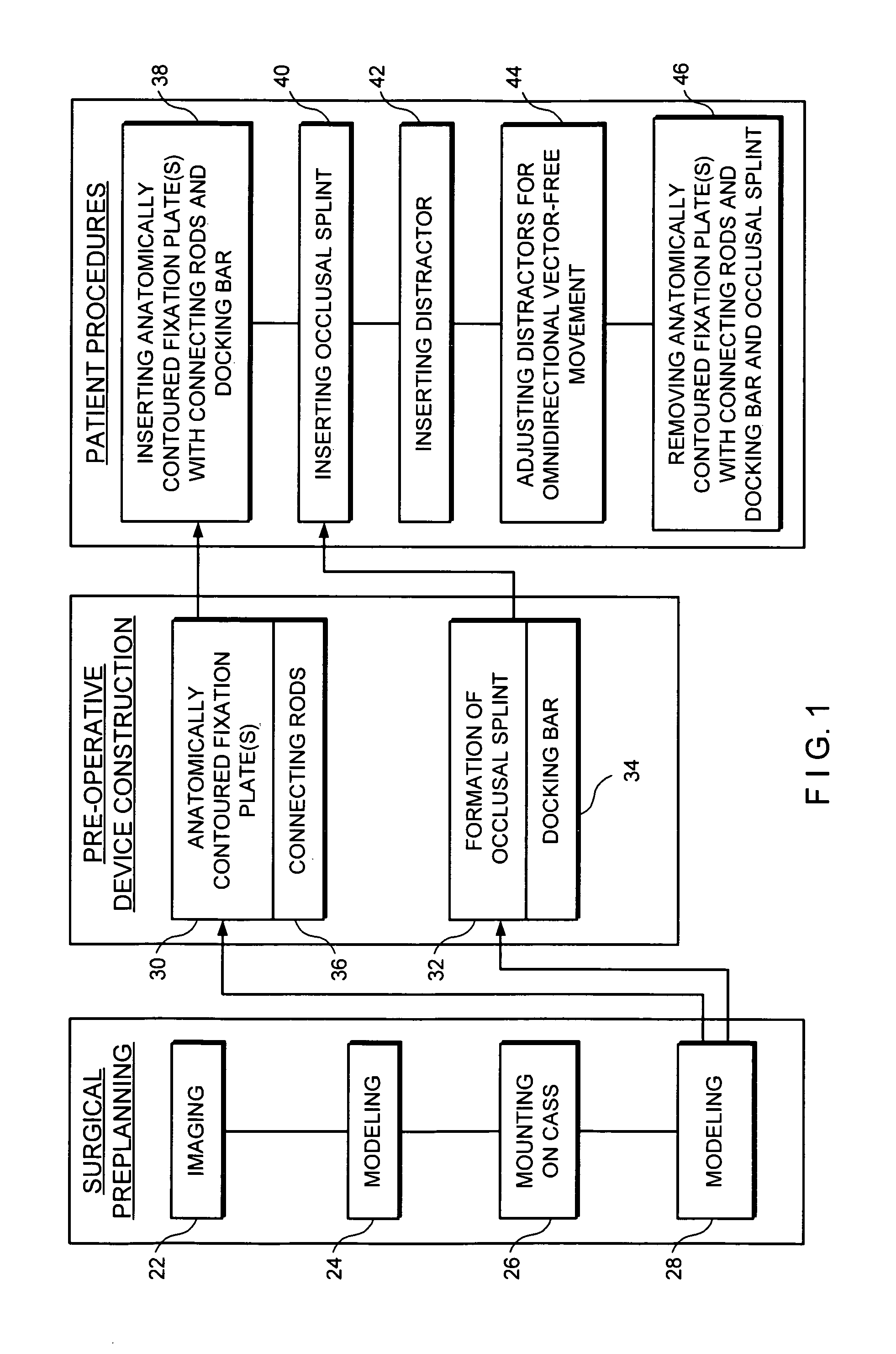
[0045]Referring to the schematic diagram of the system FIG. 1, a general overview of the new system of orthopedic surgery is now provided. Three principal divisions are apparent, namely, (1) surgical preplanning; (2) pre-operative device construction; and, (3) patient procedures.

[0046]Upon initializing the process, an IMAGING 22 of the patient is first undertaken. The IMAGING 22 step may obtain digitized data from scans of magnetic resonance imaging (MRI), X-ray, computed t...


PUM


Abstract

Intra-oral devices for distraction osteogenesis are described. Utilizing a medical model, bone-traced fixation plates with undercut portions are custom-fitted to the skeleton of the patient. To these plates rigid distraction platforms are connected. In the pre-surgical stage, skeletal segments are placed in the post-operative position and occlusal splints are constructed. The occlusal splints are modified to interengage the distraction platforms and to provide docking therefor. One or more distractors are mounted on the rigid platform and, upon operation thereof, guide the segment to the distraction endpoint. Optionally, after distraction and during consolidation, the distractors may be removed.

Description

CROSS REFERENCE TO RELATED APPLICATIONS[0001]This is a Continuation-in-Part of application Ser. No. 12 / 004,542 filed Dec. 20, 2007 entitled Computer-Aided System of Orthopedic Surgery and, further, this Application is a non-provisional of Provisional Application 60 / 885,570 filed Jan. 18, 2007 entitled Craniofacial Maxillary Custom Intra-Oral Distraction Device and of Provisional Application 60 / 899,441 filed Feb. 6, 2007, entitled Intra-Oral Mandibular Distraction Device, said applications are incorporated herein by reference.BACKGROUND OF THE INVENTION[0002]1. Field of Invention[0003]The present invention relates to intra-oral devices for craniofacial distraction osteogenesis, and, more particularly, to an intra-oral system for both maxillary and mandibular distraction osteogenesis. The system uses computer generated, for example computed tomography (CT), information to form custom-cast, bone-traced appliances so as to attain especially strong connections to the facial bones. Stabil...

Claims


Application Information

Patent Timeline
Patent Type & Authority Patents(United States)
IPC IPC(8): A61B17/00A61C3/00A61B17/58
CPCG09B23/32A61B17/663A61B2034/105G09B23/28A61B17/00
Inventor AMATO, CYRUS J.
Owner AMATO CRANIOFACIAL ENG
Why Eureka
Try Eureka