Downlink while pumps are off

a technology of downlink and pump, which is applied in the field of downlink systems, can solve the problems of inefficiency of downlink, length of time involved in sending a downlink, and the inability to send downlink signals

Active Publication Date: 2012-10-09
SCHLUMBERGER TECH CORP
View PDF41 Cites 14 Cited by
  • Summary
  • Abstract
  • Description
  • Claims
  • Application Information

AI Technical Summary

Problems solved by technology

Drawbacks to mud pulse telemetry include the temporary interruption of drilling operations to allow mud pumps at the surface to be cycled on and off, which provides the pulses.
Further drawbacks to mud pulse telemetry include that downlink signals may not be sent when the mud pumps are cycled off.
Additional drawbacks include the length of time involved in sending a downlink because of the measured depth of deviated wells as well as inefficiencies in downlinks when gas is entrained in the drilling mud.
Drawbacks also include the cost of surface equipment and maintenance for mud bypass modulators and the like.
In addition, drawbacks include the time that it takes to send information to the downhole tool and the surface equipment cost.
Because the mud pumps are large mechanical systems, a large inertia is involved, and therefore the flow rate may not be changed quickly, which results in an inefficiently long time to send the downlink commands.
Drawbacks to such method include the considerable time and increased cost of the surface equipment, installation and maintenance.
It also poses safety risks on the rig floor and added costs to mitigate the safety issues.
Drawbacks to the conventional electromagnetic telemetry systems include that the downlink signals reaching the downhole tool are typically weak and may not be sensed while the uplink telemetry is being transmitted.
Further drawbacks in many cases of mud pulse telemetry and electromagnetic telemetry include deployment of special sensors in the downhole tool to detect signals, which may increase the cost of the system.

Method used


Image

  • Downlink while pumps are off
  • Downlink while pumps are off
  • Downlink while pumps are off

Examples


Embodiment Construction

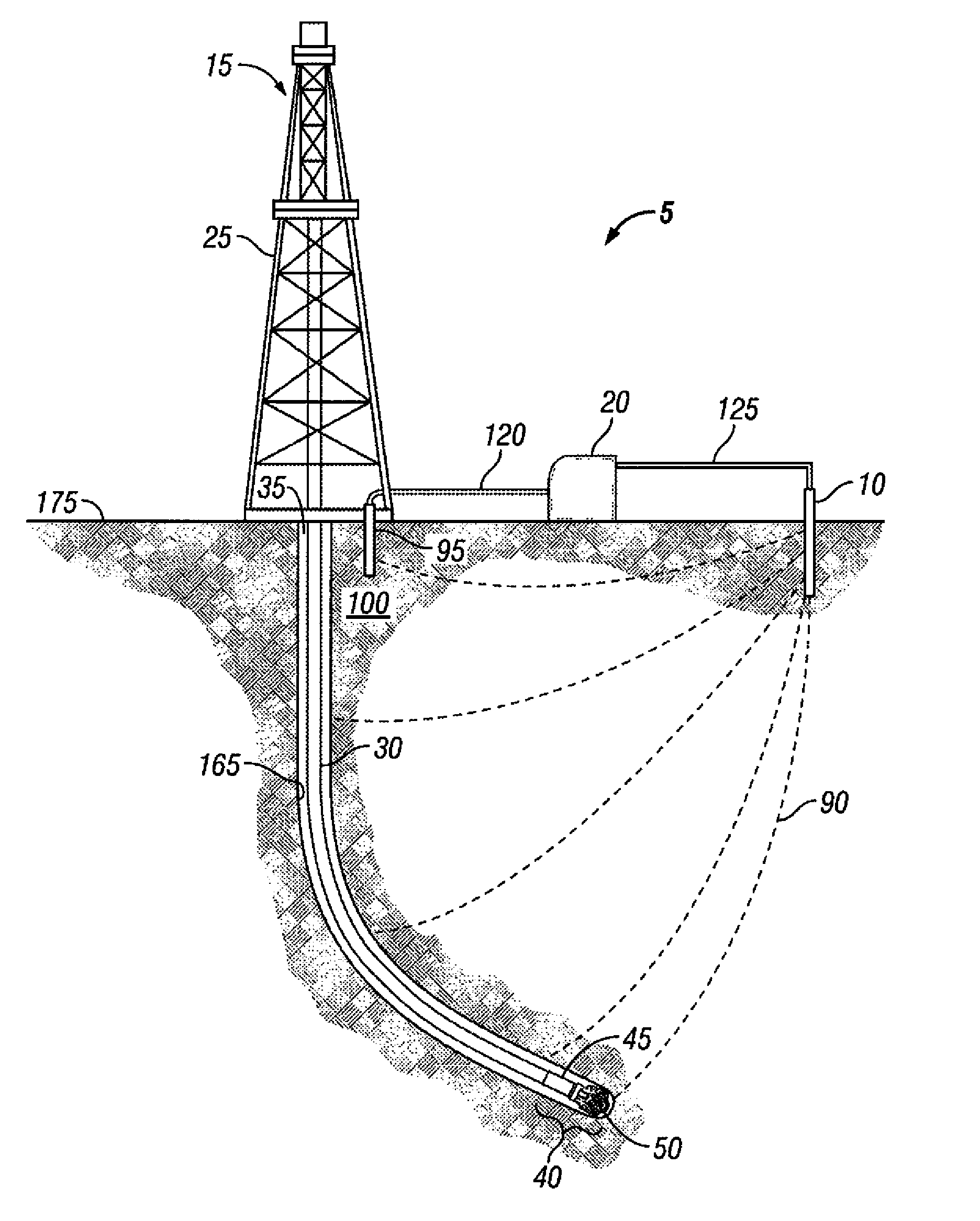
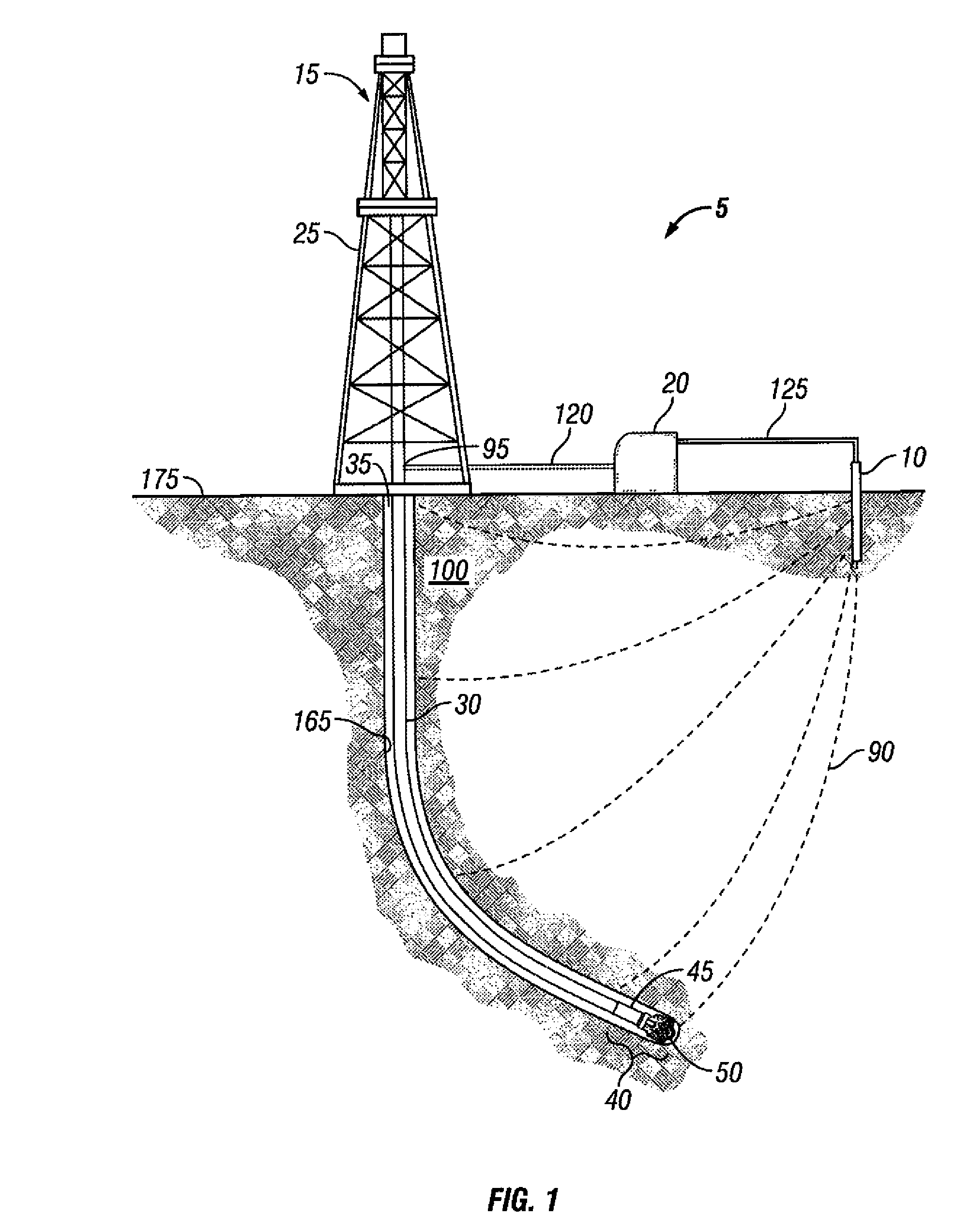
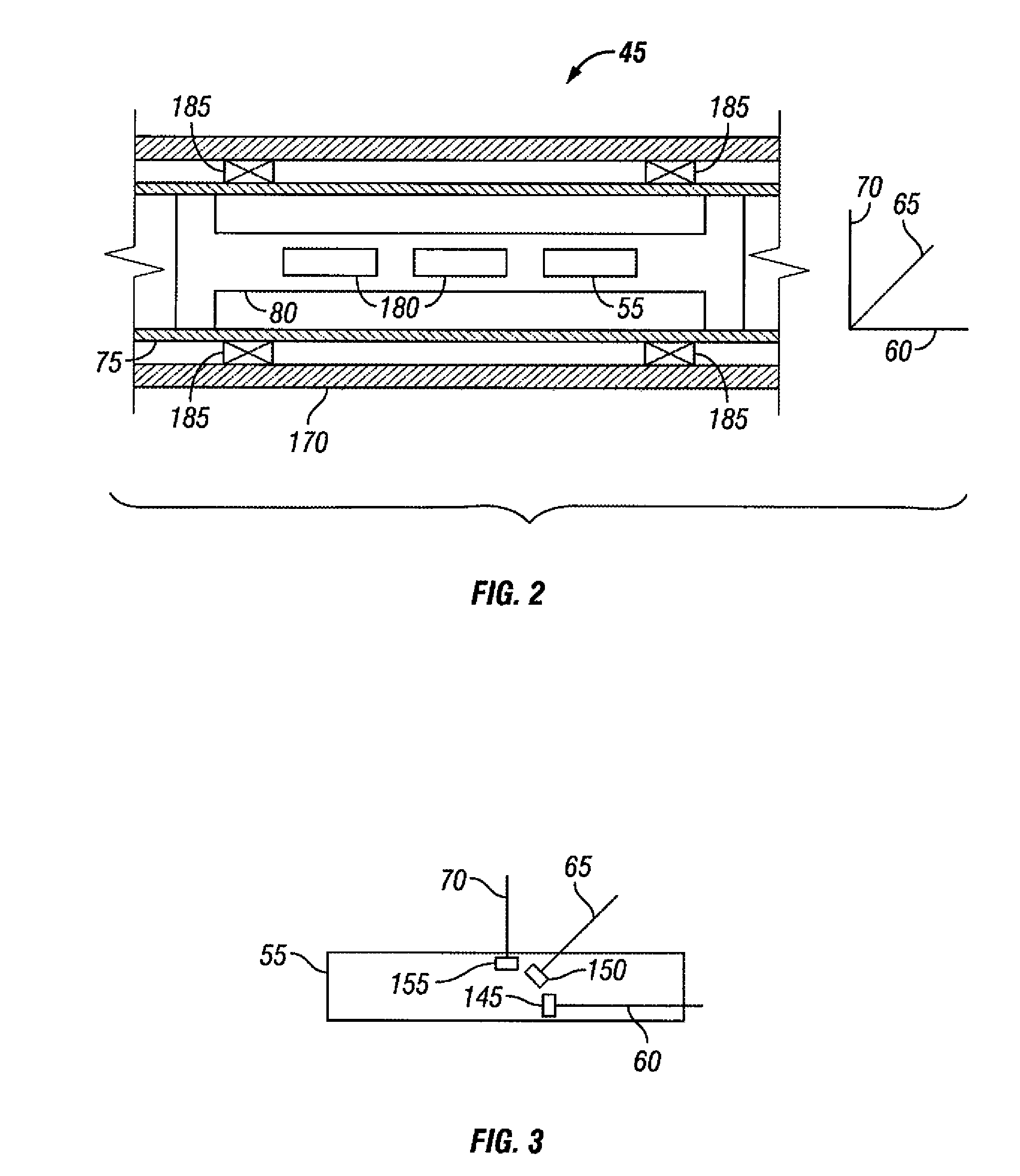
[0010]These and other needs in the art are addressed in one embodiment by a telemetry system for communicating with a downhole tool in a wellbore. The telemetry system includes a first electrode. A modulated electric current flows from the first electrode through a formation to the downhole tool. The telemetry system also includes a downlink box, which provides the modulated electric current to the first electrode. The downhole tool has a sensor unit, which detects the modulated electric current. In addition, the telemetry system includes a second electrode that allows the modulated electric current to return to the downlink box. The telemetry system further includes an uplink telemetry, which does not comprise electromagnetic telemetry.

[0011]In another embodiment, these and other needs in the art are addressed by a method of communicating with a downhole tool in a wellbore. The method includes providing an electric current. In addition, the method includes modulating the electric c...


PUM


Abstract

A system and method for communicating with a downhole tool is disclosed. In one embodiment, a telemetry system for communicating with a downhole tool in a wellbore includes a first electrode. A modulated electric current flows from the first electrode through a formation to the downhole tool. The telemetry system also includes a downlink box, which provides the modulated electric current to the first electrode. The downhole tool comprises a sensor unit, which detects the modulated electric current. The telemetry system includes a second electrode that allows the modulated electric current to return to the downlink box. The telemetry system also includes an uplink telemetry, wherein the uplink telemetry does not comprise electromagnetic telemetry. In some embodiments, the downlink may be operated while mud pumps are turned off. The downlink may also be operated while the downhole tool is sending uplink telemetry by a method other than electromagnetic current.

Description

BACKGROUND OF THE INVENTION[0001]1. Field of the Invention[0002]This invention relates to the field of downlink systems and more specifically to downlink systems for communicating with a downhole tool in a wellbore.[0003]2. Background of the Invention[0004]Wells are generally drilled into the ground to recover natural deposits of hydrocarbons and other desirable materials trapped in geological formations in the Earth's crust. A well is typically drilled using a drill bit attached to the lower end of a drill string. The well is drilled so that it penetrates the subsurface formations containing the trapped materials for recovery of the trapped materials. The bottom end of the drill string conventionally includes a bottomhole assembly that has sensors, control mechanisms, and associated circuitry. As the drill bit is advanced through the formation, drilling fluid (e.g., drilling mud) is pumped from the surface through the drill string to the drill bit. The drilling fluid exits the dril...

Claims


Application Information

Patent Timeline
Patent Type & Authority Patents(United States)
IPC IPC(8): E21B47/12G01V3/34
CPCE21B47/121G01V11/002E21B47/125H04B13/02
Inventor MEHTA, SHYAM B.PHILLIPS, WAYNEFOLLINI, JEAN-MARC
Owner SCHLUMBERGER TECH CORP
Why Eureka
Try Eureka