

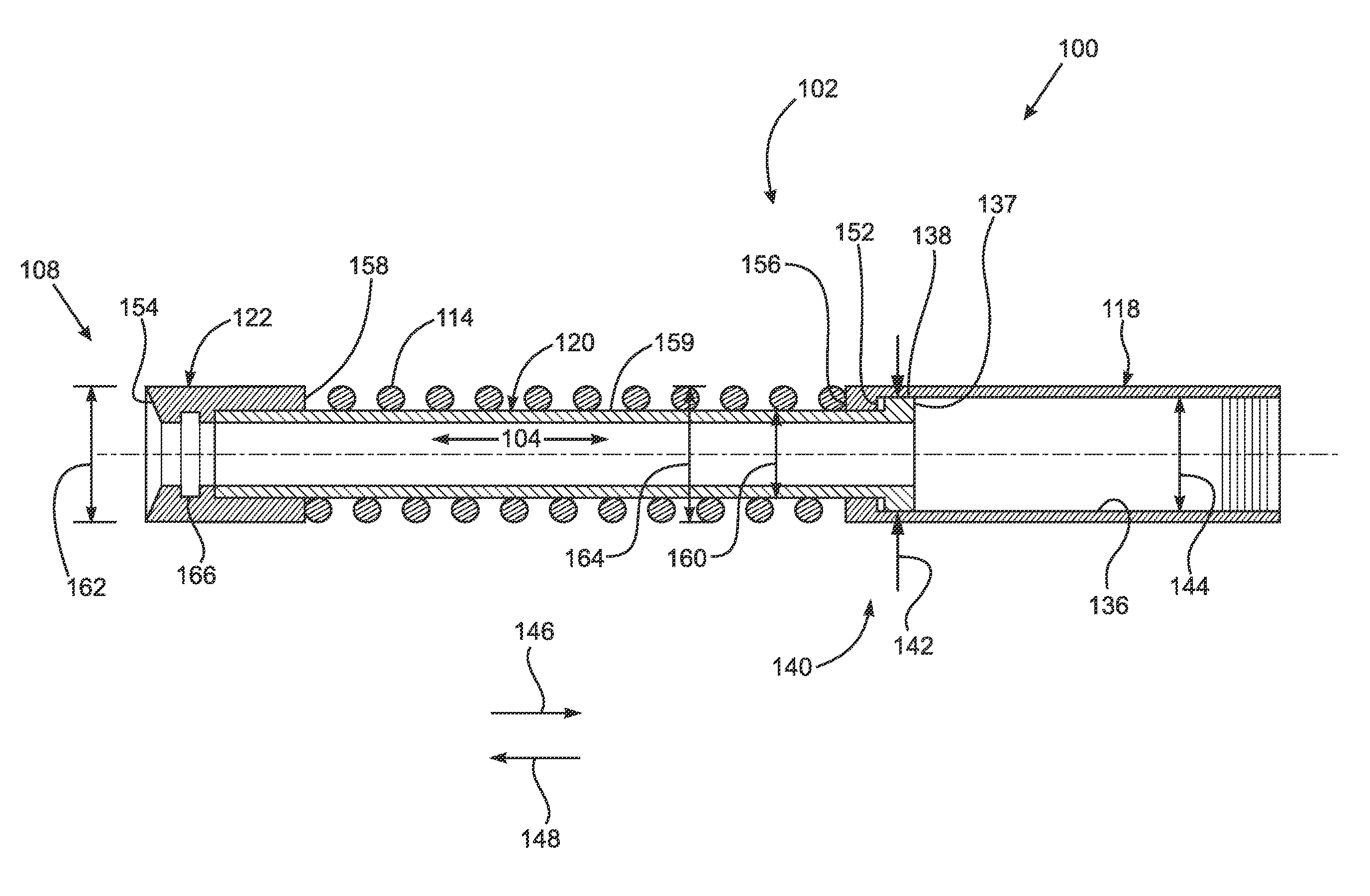
Damping and sealing device for a well pipe having an inner flow passage and method of using thereof
a sealing device and well pipe technology, applied in the direction of sealing/packing, borehole/well accessories, positive displacement liquid engines, etc., can solve the problem of limiting the area available for flow past the bumper spring, and achieve the effect of sufficient shock protection and maximum flow
- Summary
- Abstract
- Description
- Claims
- Application Information
AI Technical Summary
Benefits of technology
Problems solved by technology
Method used
Image

Examples
Embodiment Construction
[0021]At the outset, it should be appreciated that like drawing numbers on different drawing views identify identical, or functionally similar, structural elements of the invention. It is to be understood that the invention as claimed is not limited to the disclosed aspects.
[0022]Furthermore, it is understood that this invention is not limited to the particular methodology, materials and modifications described and as such may, of course, vary. It is also understood that the terminology used herein is for the purpose of describing particular aspects only, and is not intended to limit the scope of the present invention, which is limited only by the appended claims.
[0023]Unless defined otherwise, all technical and scientific terms used herein have the same meaning as commonly understood to one of ordinary skill in the art to which this invention belongs. Although any methods, devices or materials similar or equivalent to those described herein can be used in the practice or testing of...
PUM
 Abstract
Description
Claims
Application Information